ZXM-Phoenix |
RU |
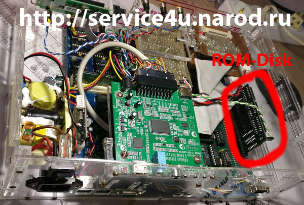
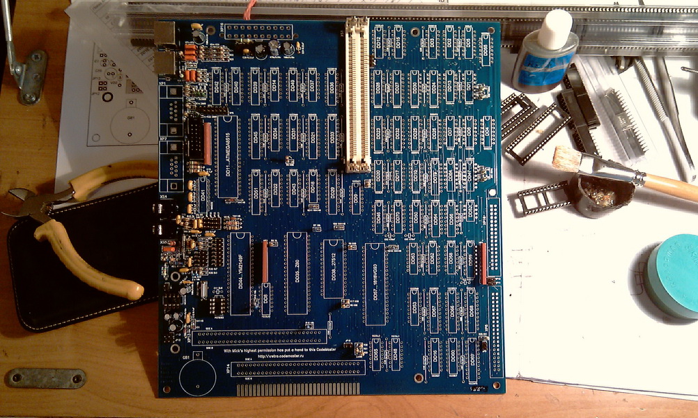
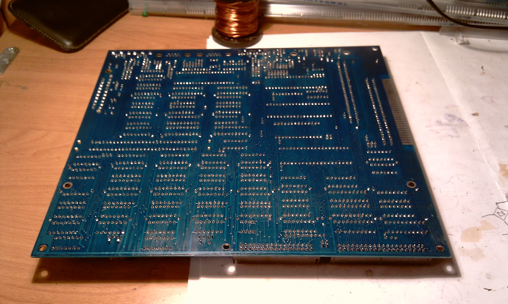
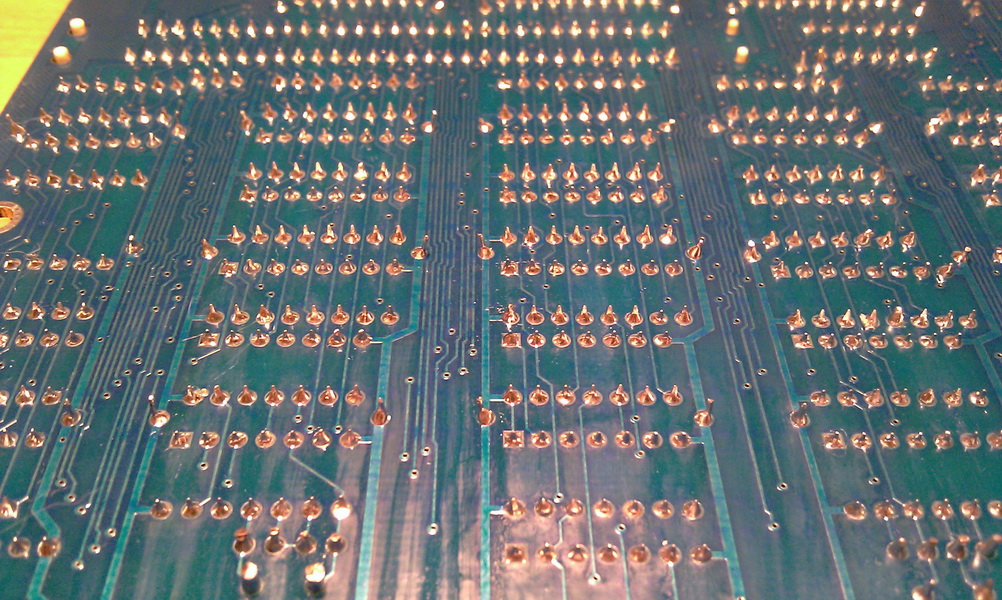
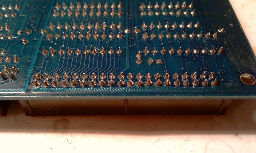
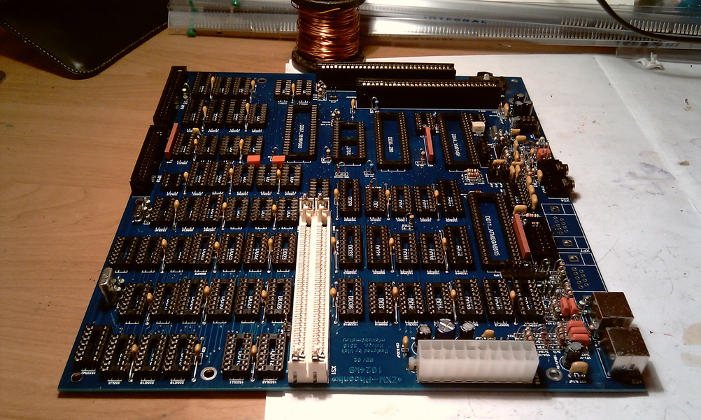
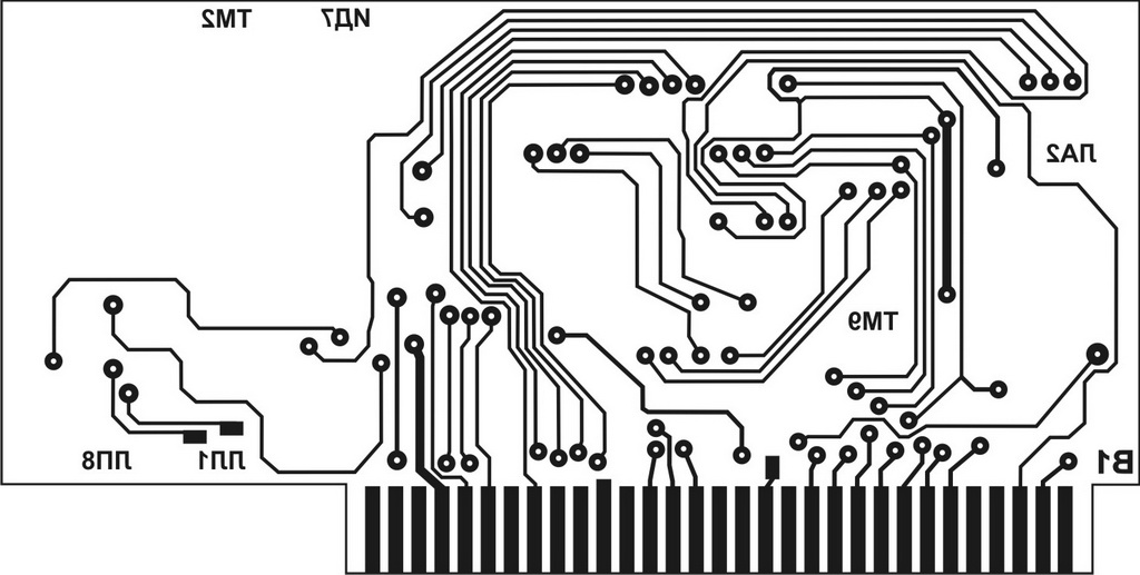
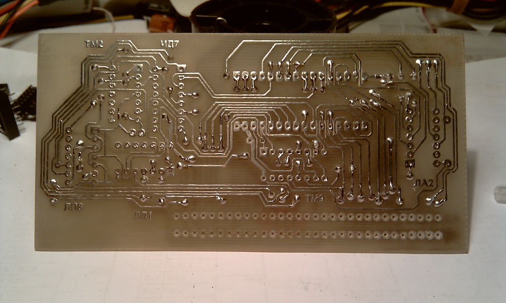
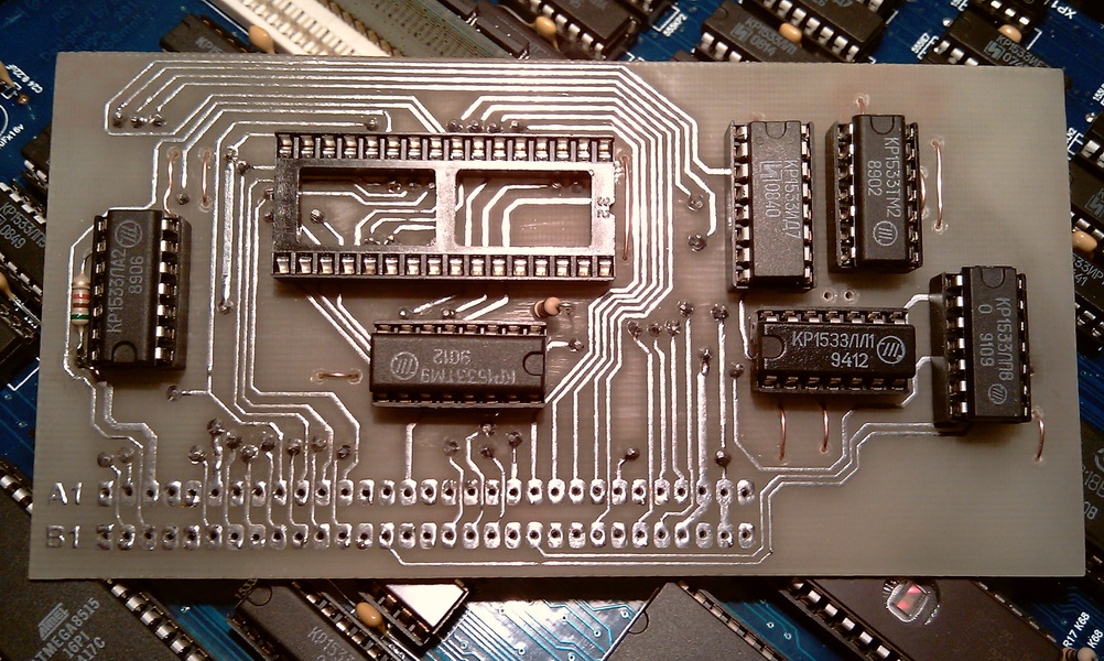
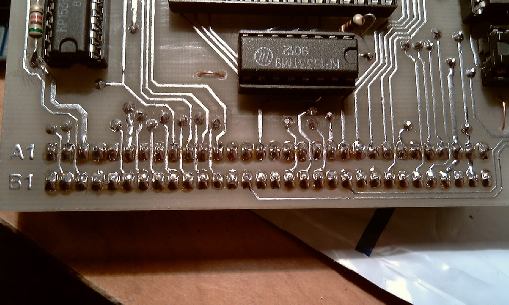
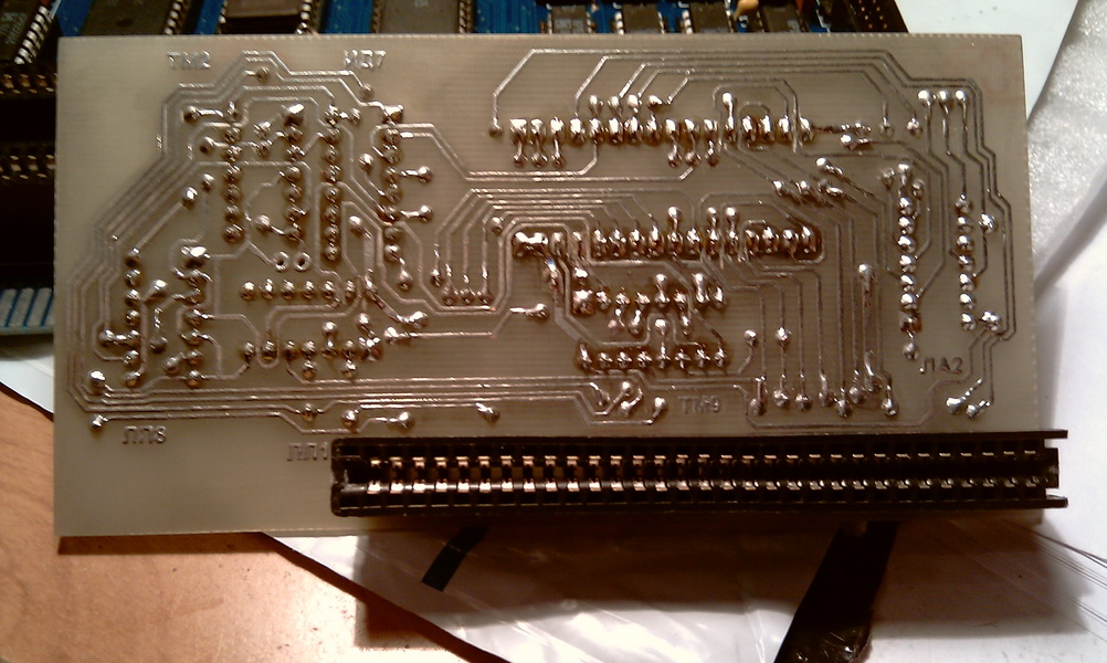
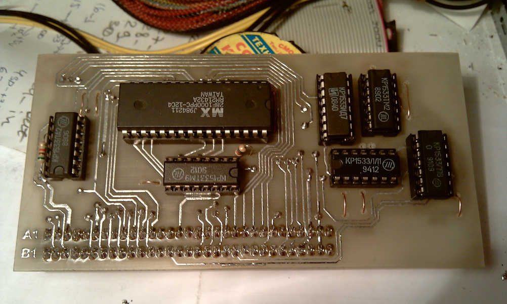
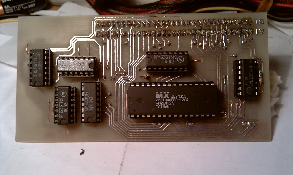
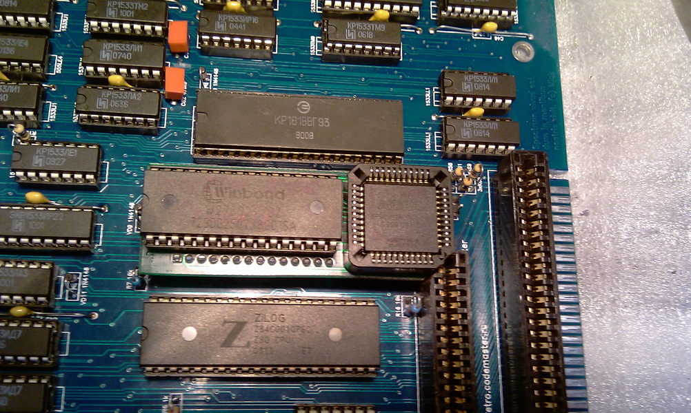
It all started with the purchase of a factory-made printed circuit board on the forum zxpk.ru. Like 14 other people, I became one of the owners of the printed circuit board of the ZXM-Phoenix 1.02 computer. Official page about Phoenix here, you can see the characteristics there. Straight to the point. On the advice of Prusak'a, it was decided to put everything on the panel, because if that - then this option it will save you time, money and the printed circuit board will be healthier, and most importantly, your nerve cells will not suffer such global losses than all microcircuits would be soldered directly into the board. First, I soldered all the looseness, ala resistance, capacitance, diodes ... After - the panels. I inserted all the microcircuits according to the silk-screen printing (there is one inaccuracy). The first power supply, the Phoenix takes its first breath and ... the bird came to life ...
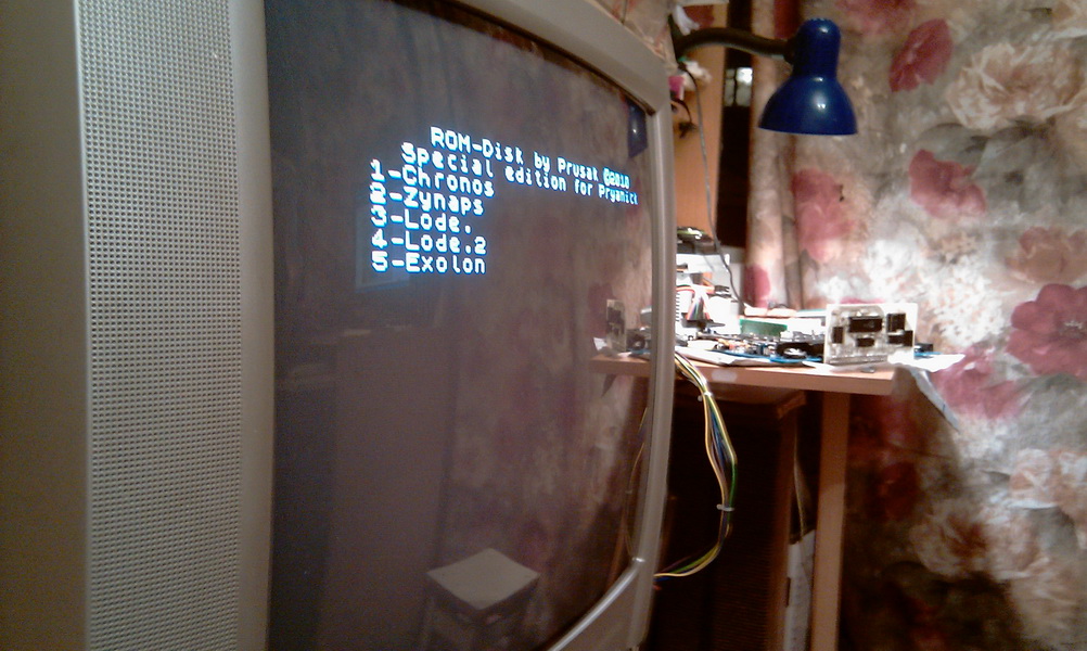
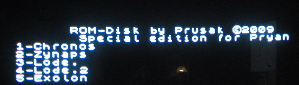
ROM-Disk
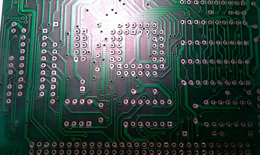
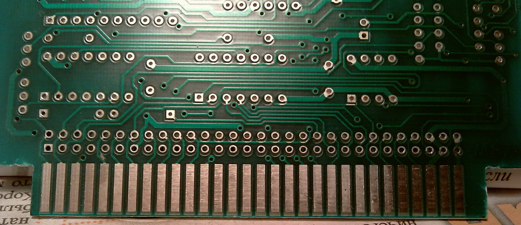
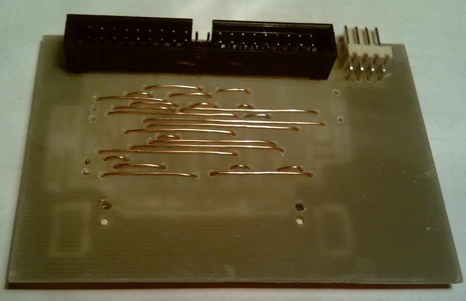
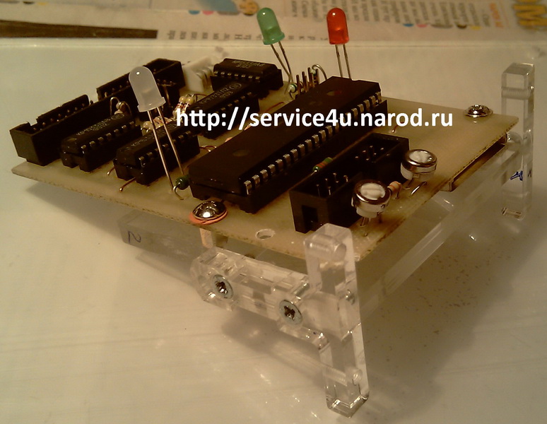
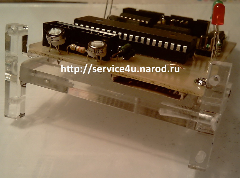
As in the computer "Leningrad-2" it was attractive to make a ROM-Disk. Prusak didn't take long with this and issued a universal ROM-Disk scheme. This circuit will work on any computer equipped with a ZX-bus connector. And even two ROM-Disk cards inserted into different slots on the same computer will work without problems. So, the scheme of the ROM-Disk and the board for its manufacture at home:
: : ROM-Disk : :
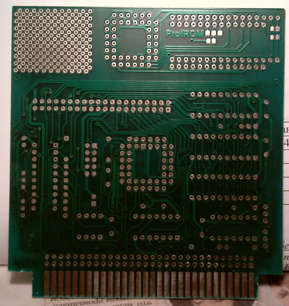
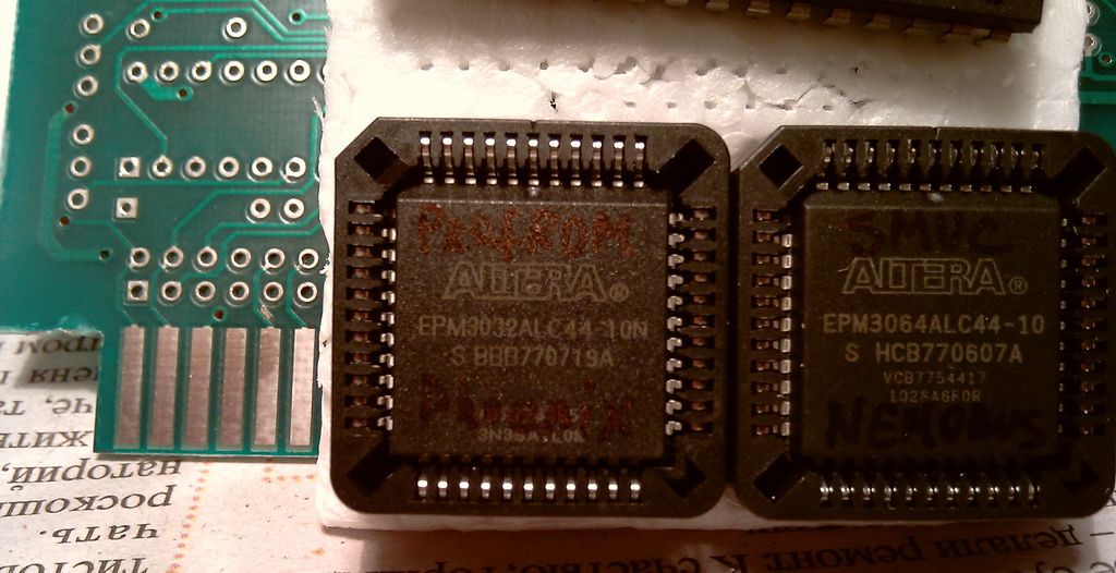
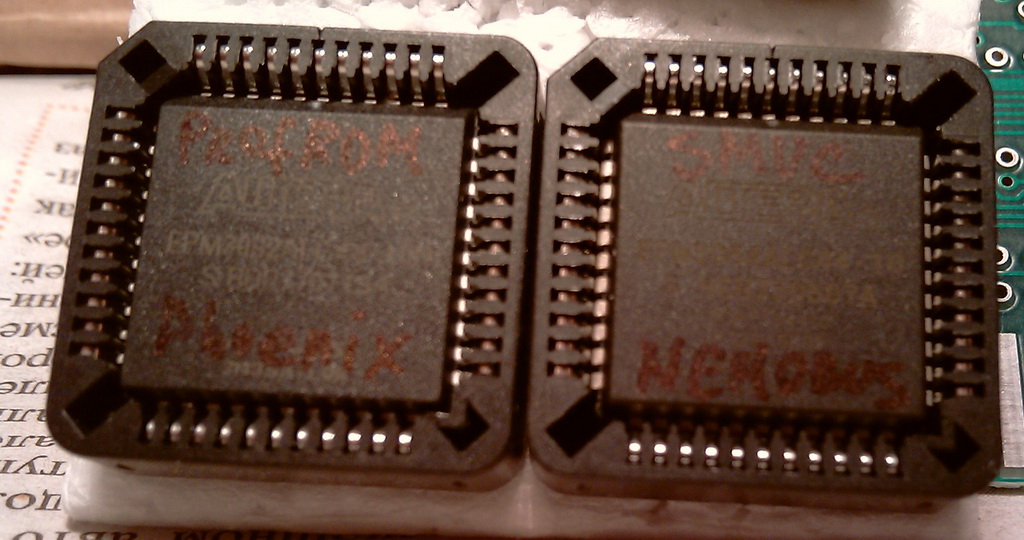
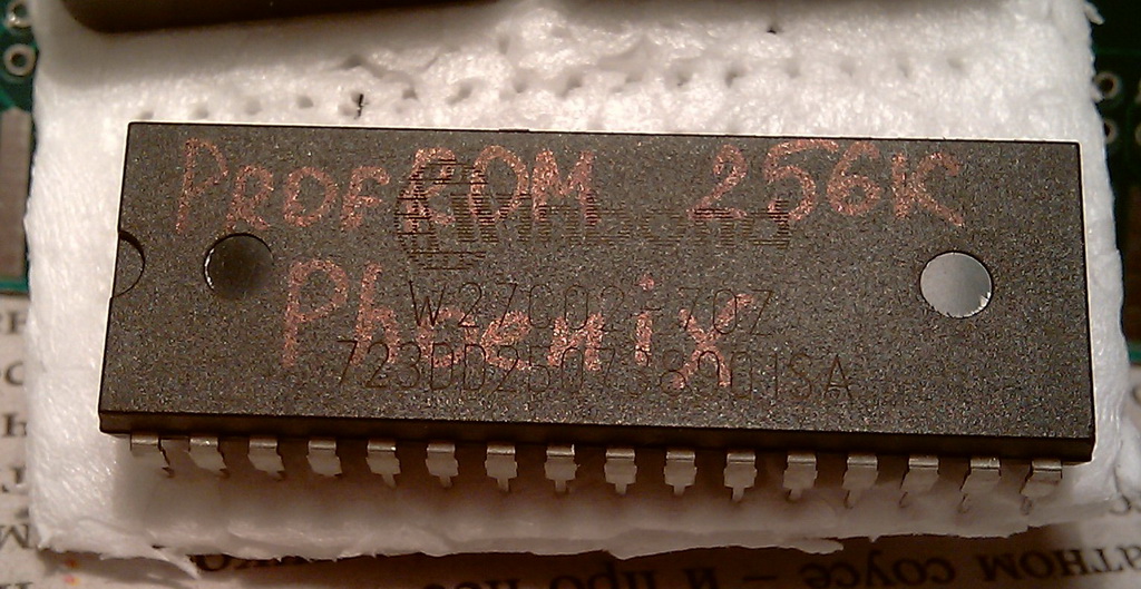
SMUС + ProfROM
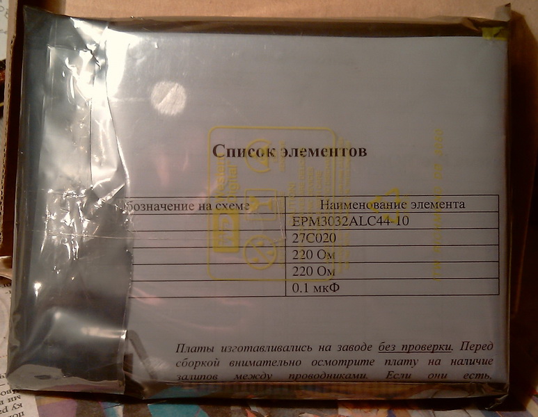
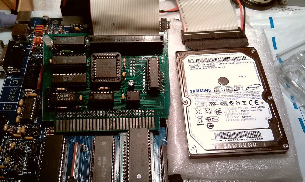
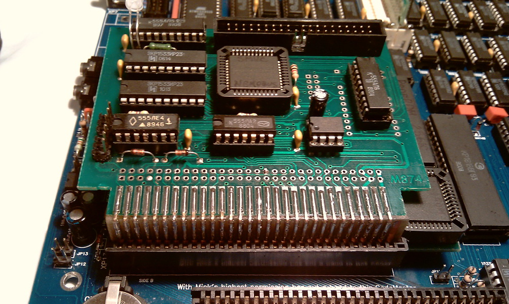
You can read more about what it is on the website zxpk.ru. From the very beginning, I planned to assemble SMUC and ProfROM on loose, in Eagle I even drew schematics and even corrected scarves after automatic wiring - a matter of one evening. But then it became clear - that the manufacture of boards in the factory will cost a pretty penny. After that, the crumbling was put an end to and I ordered factory scarves, two Alter's, a flash ROM and some other little things for SMUC'a and ProfROM. Next, the photo in order of action.
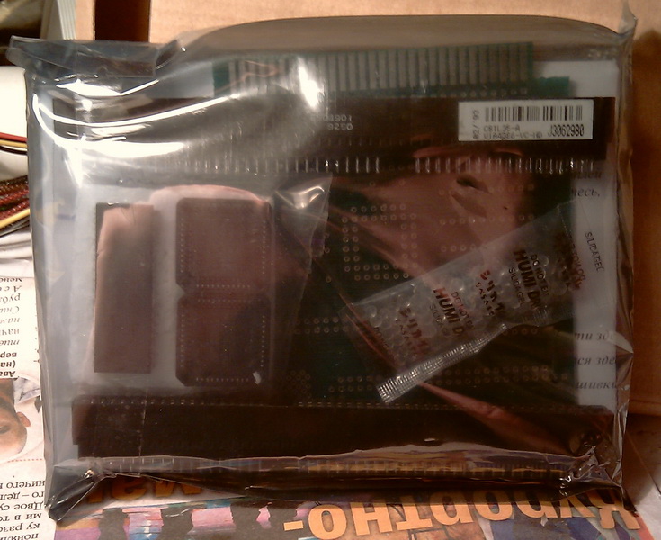
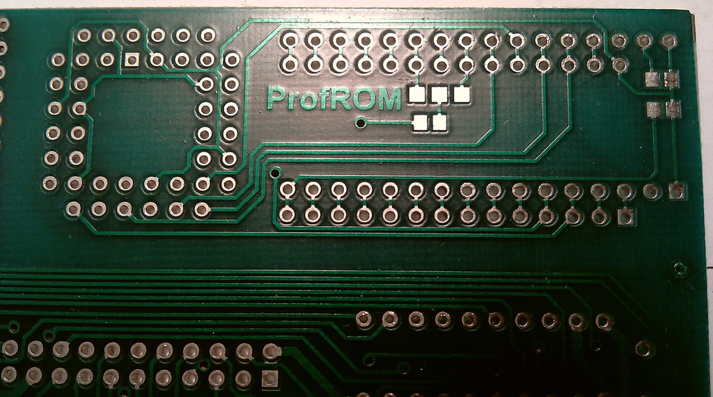
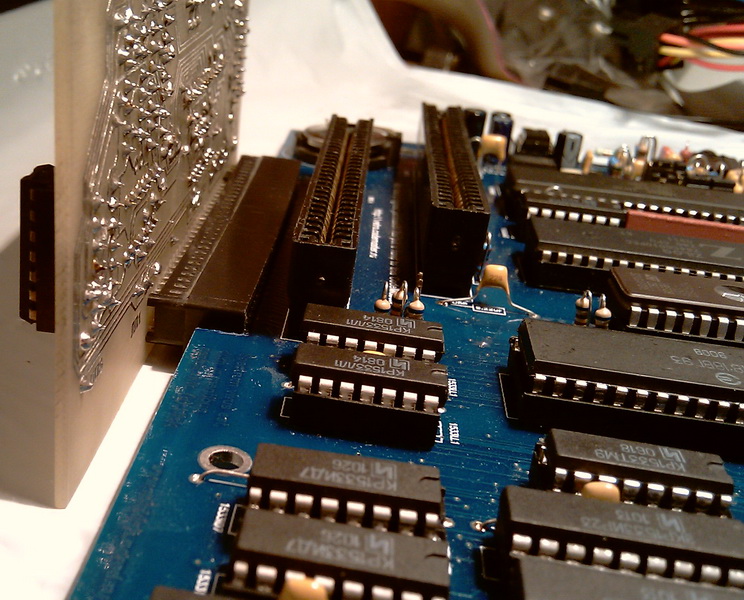
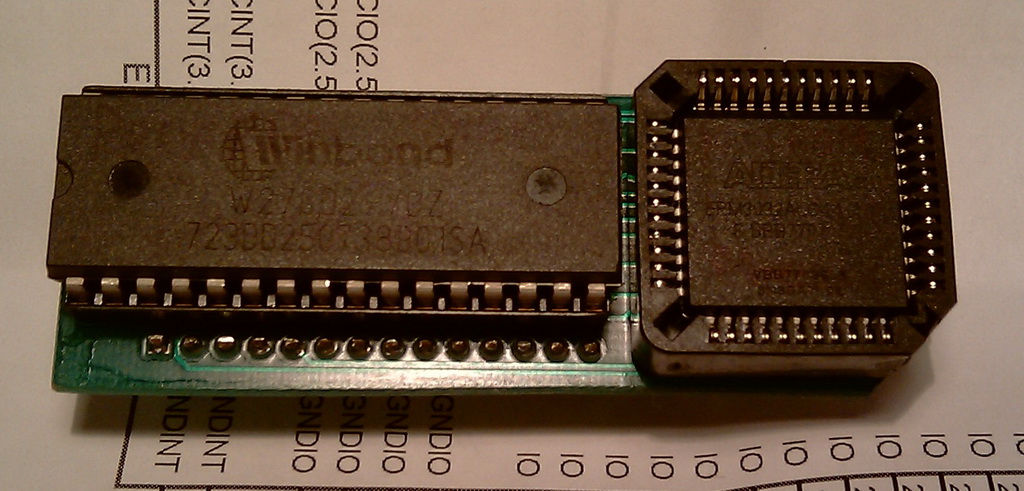
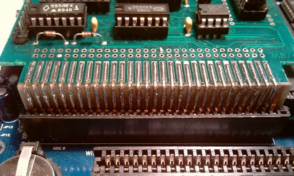
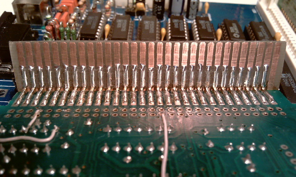
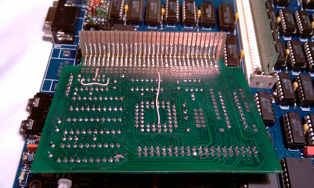
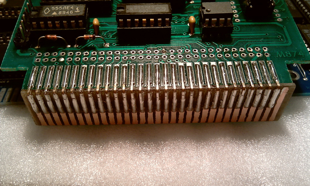
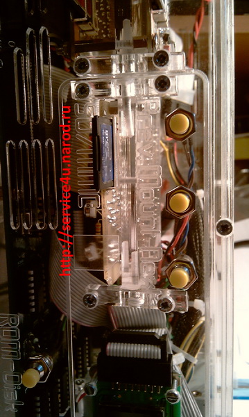
The boards are made with high quality, after checking both sides for sticking, etc., both stuffed and soldered. Everything started without any problems. True, there is one nuance. This is the installation of ProfROM scarves in ZXM-Phoenix 1.02. In words, I had to cut off the corner of the SMUC scarf and the corner of the ZX-BUS connector. Further, in the photo, it will be more clear.
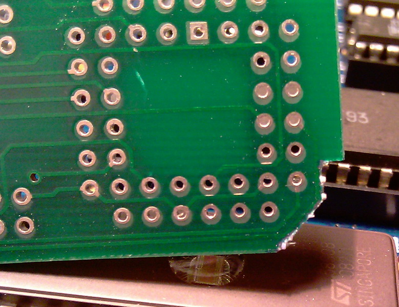
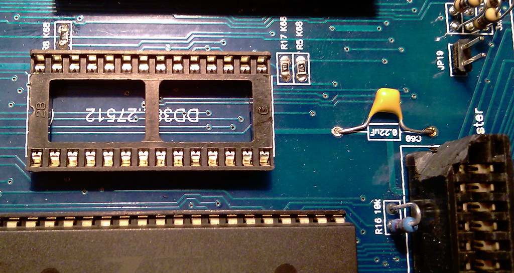
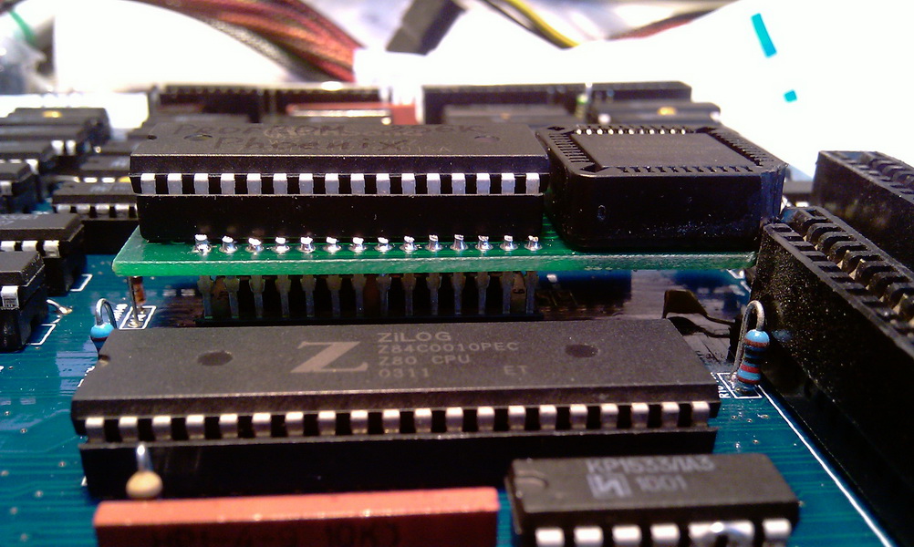
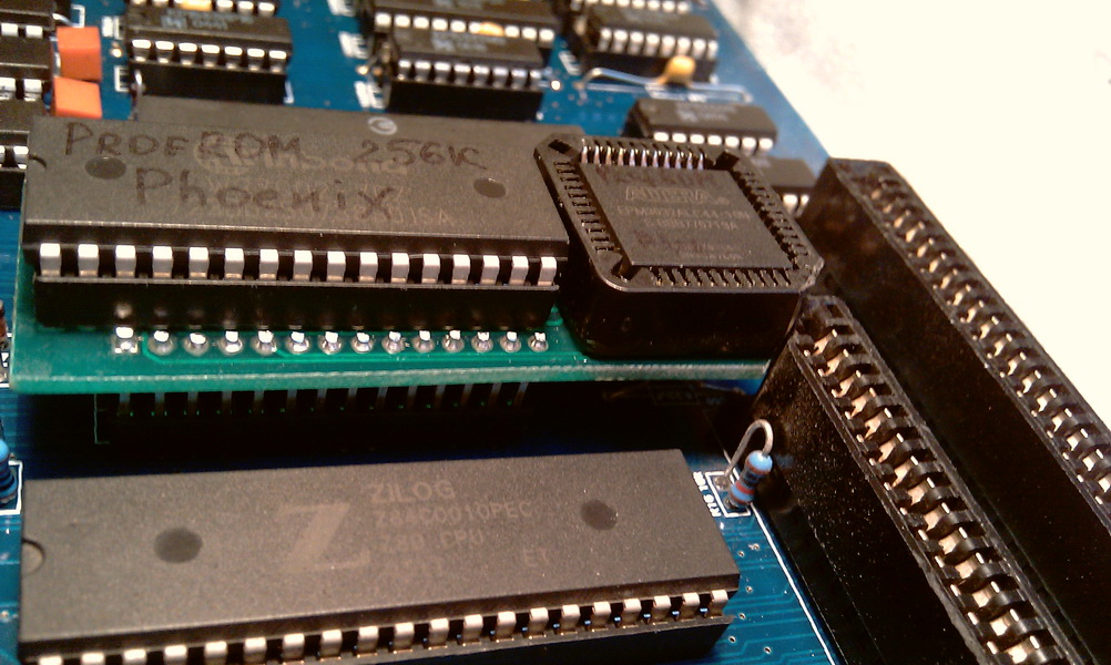
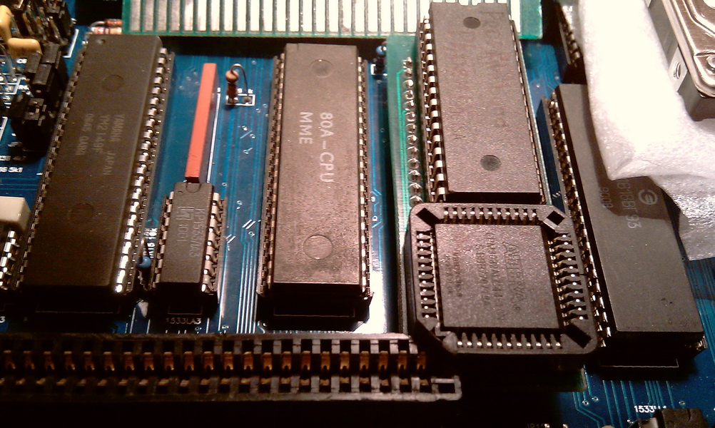
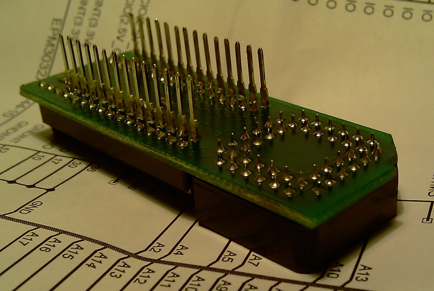
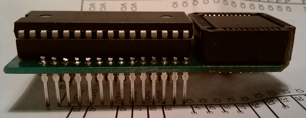
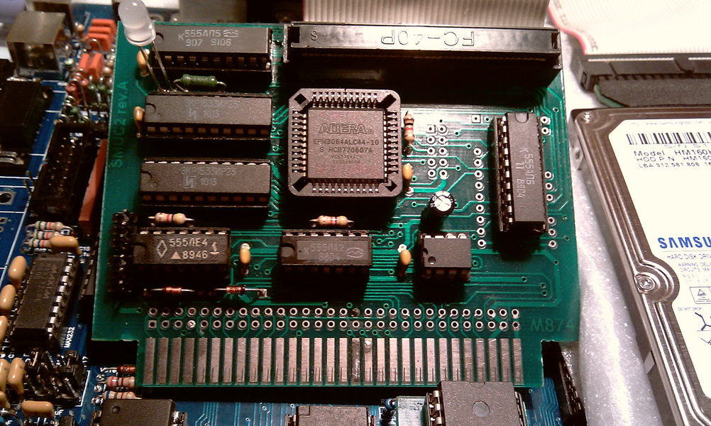
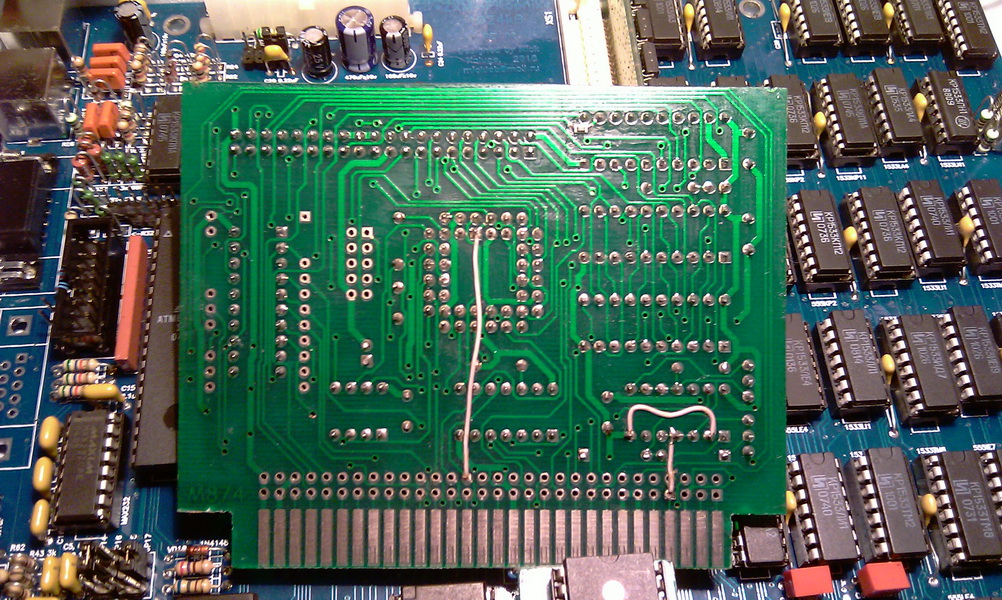
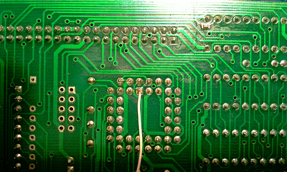
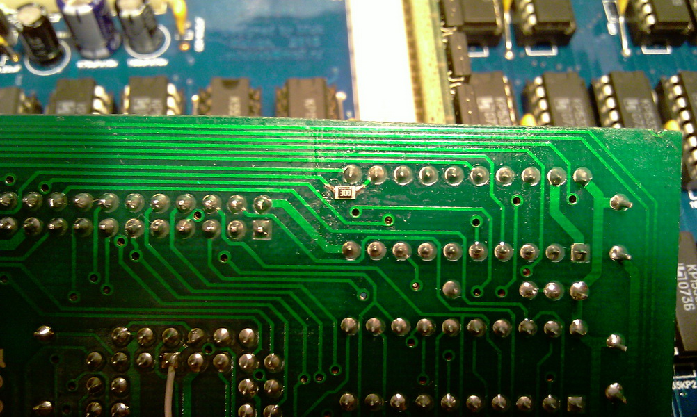
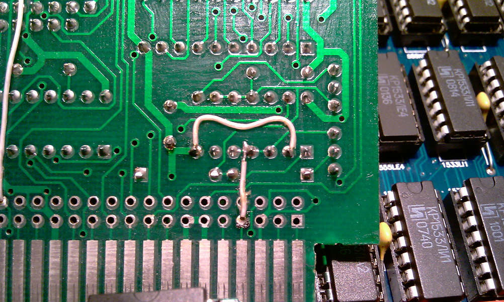
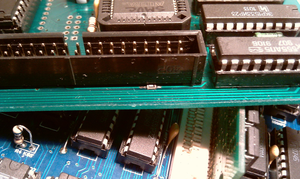
There are actually two moments here. First - if you have a ZX-BUS connector closest to the processor, then the ProfROM scarf will not be so easy, it simply will not fit. Therefore, with a dremel, I simply sanded the protruding corner of the connector and the corresponding corner of the ProfROM scarf and made it so that when the ProfROM board was seated in the ROM bed, there was a small gap between the Alter panel and the polished part of the ZX-BUS connector. The second - three output resistances, with a value of K68, I soldered and soldered SMD 0603 K47 there in order not to bend or tilt the output resistances to the Phoenix board. I didn’t solder the 0.22 cap, just put it gently on the Phoenix scarf. As conclusions for installing the ProfROM board, I used contacts from the SNP connector. I shortened them slightly in length in order to put the ProfROM scarf as low as possible.
We carry out improvements according to the instructions - a pair of jumpers and resistances.
We insert the SMUC board into the ZX-BUS connector, the ProfROM board is already installed. We connect a hard drive or CF through an adapter to SMUC, turn it on and check how everything works for us. To reduce the height of the case, I install the SMUC board lying down.
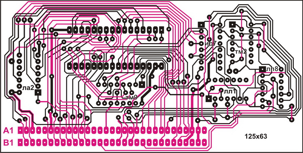
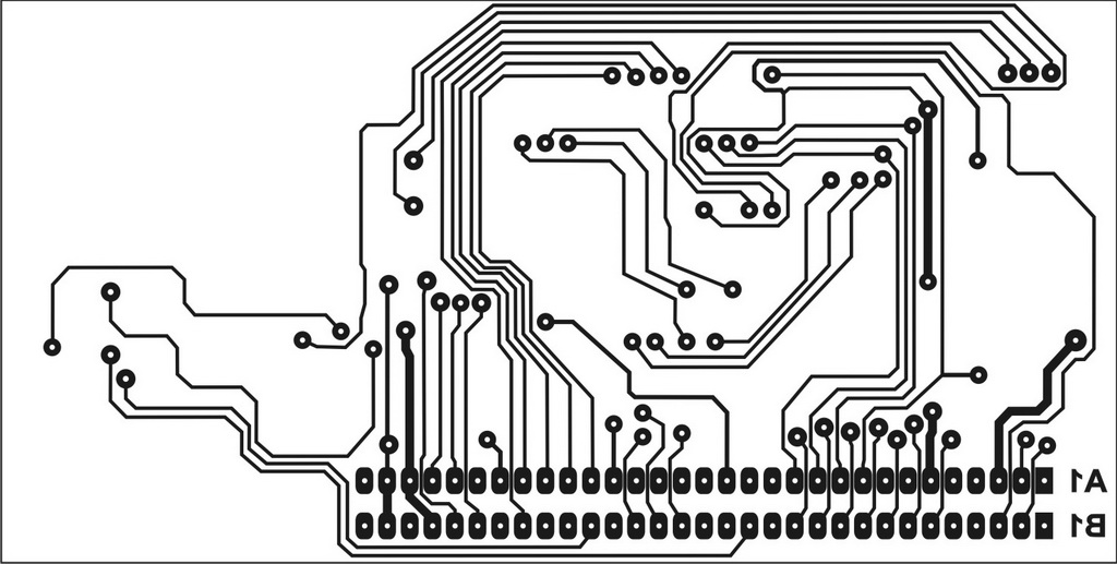
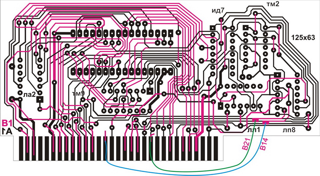
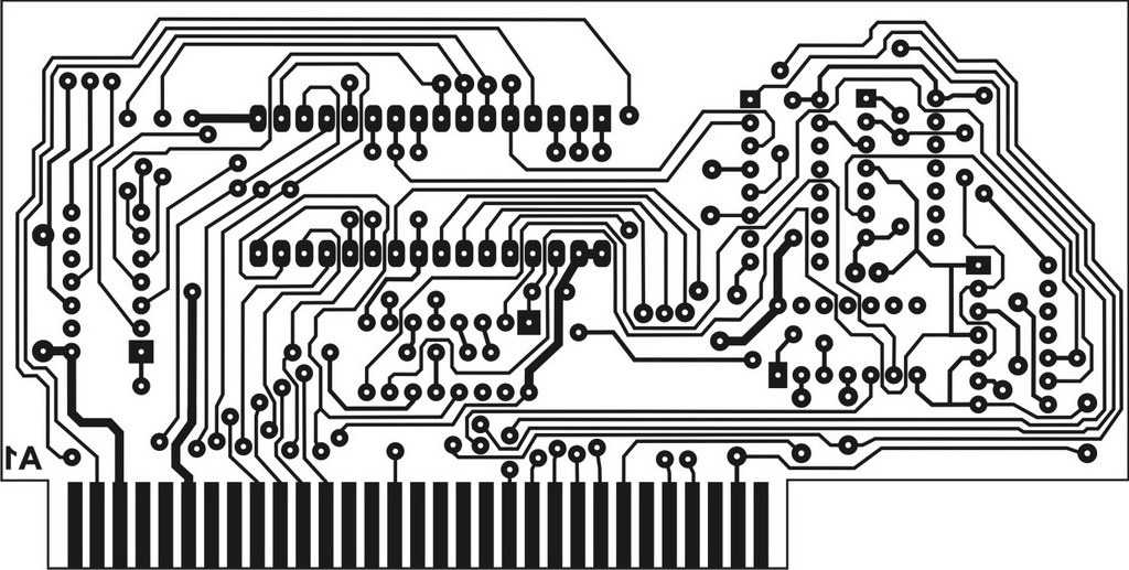
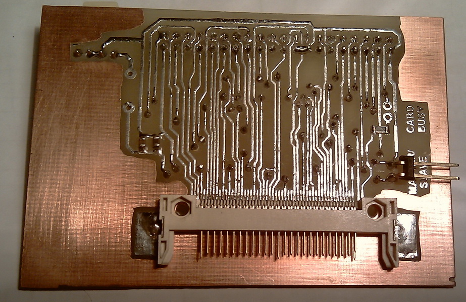
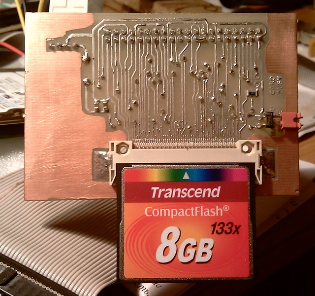
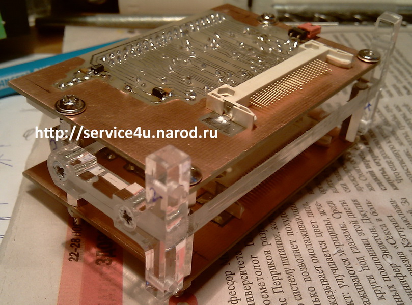
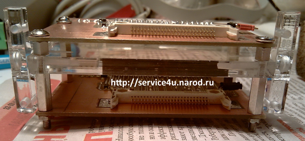
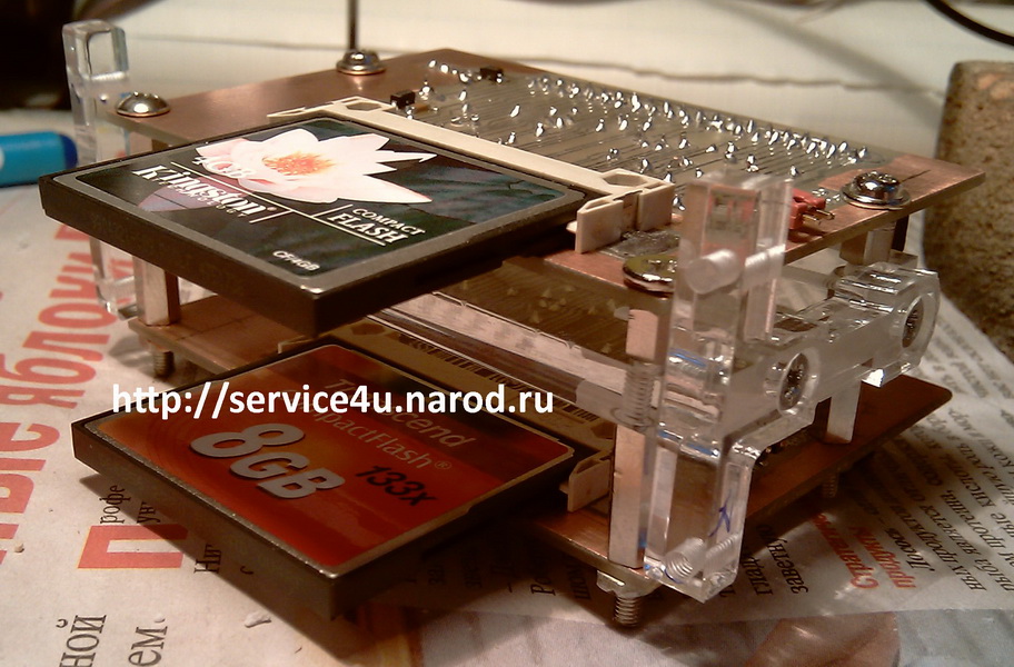
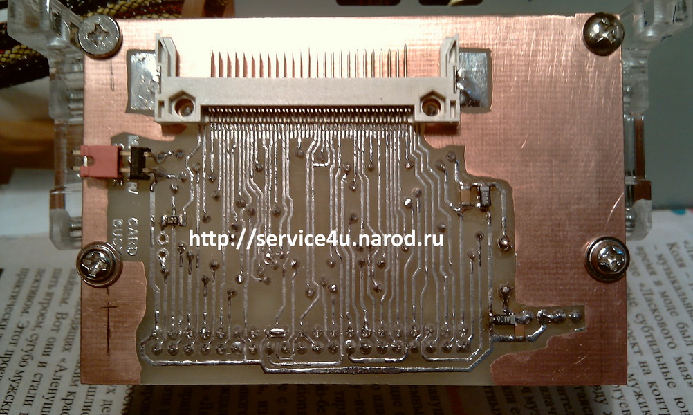
To connect the FAT media, I use the NEMO IDE controller built into the Phoenix. I will not put the Winchester there, but I will put the CF-> IDE adapter. To make an adapter, you can dig into the Internet, there is material there. You can take the template that I did. Next, a photo and a diagram of the adapter. The adapter board is not mine, I found it somewhere on the net, I just circled it in the corel, tk. the original was either in GIF'e or in JPEG'e, added something and that's all, perhaps. The source code for the CF->IDE adapter board in CorelDrawX3 format is here. Jumper on the diagram - choice between MASTER (jumper closed) or SLAVE (jumper open), the LED indicates the access to the CF card.
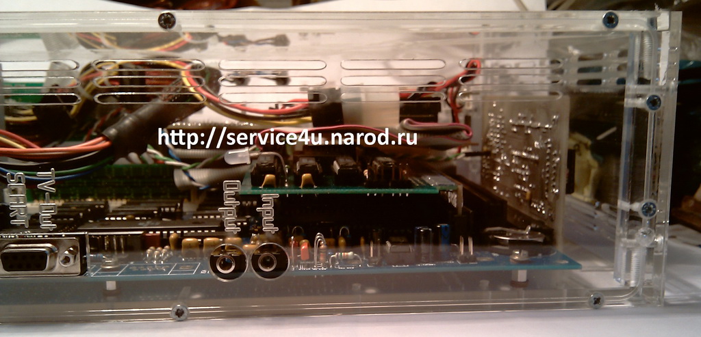
ZXM-Phoenix. Case.
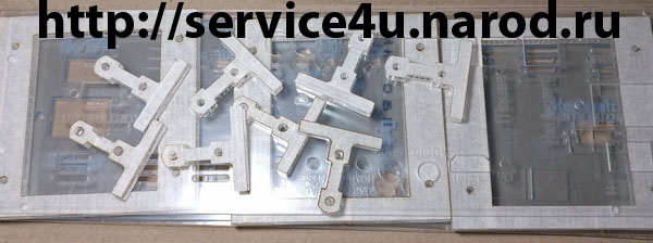
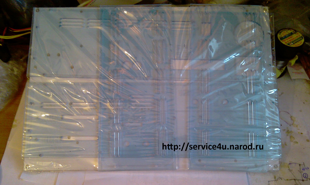
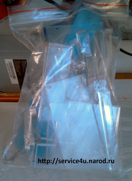
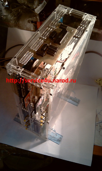
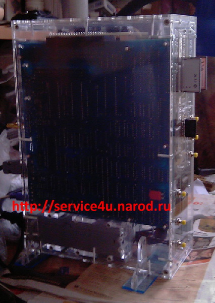
As in the case of Leningrad-2, I decided to make a case from plexiglass of various thicknesses using a proven laser cutting method. I drew a drawing, sent it for cutting and engraving, the next day I had a cut case in the form of a bag with panels and a bag with small details.
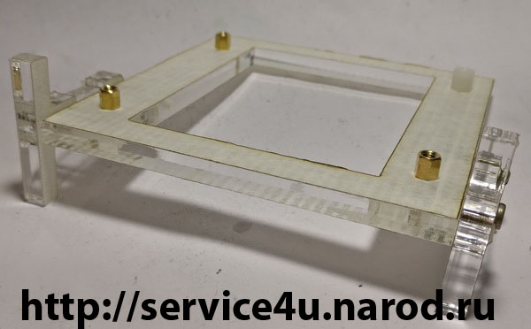
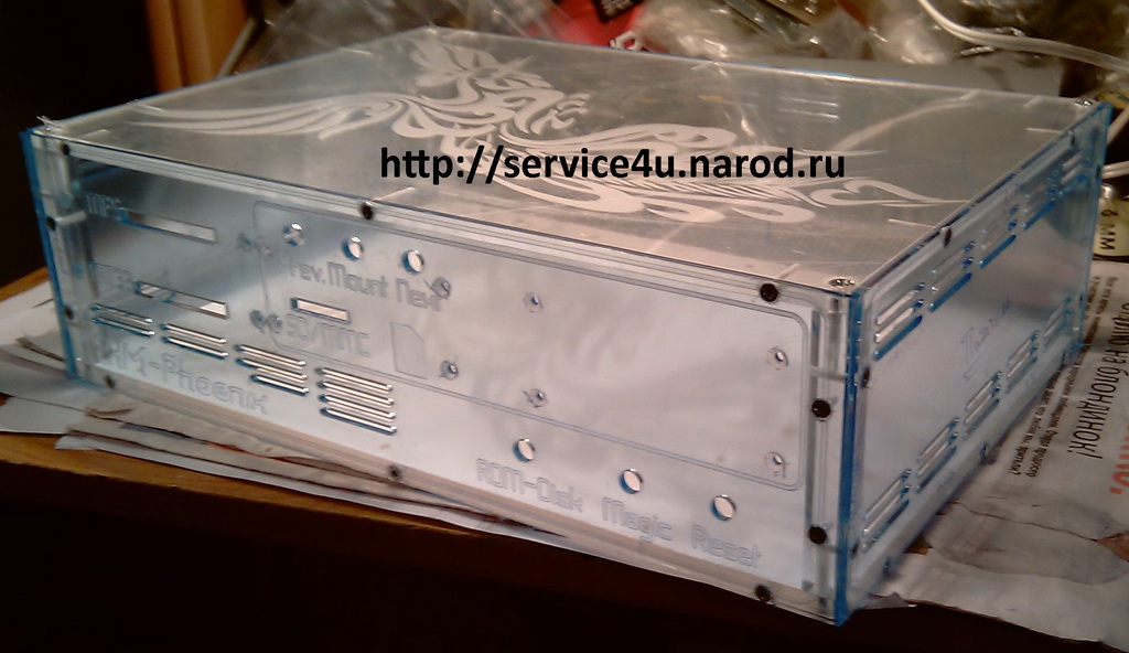
Preliminary assembly of the body to check if there are jambs.
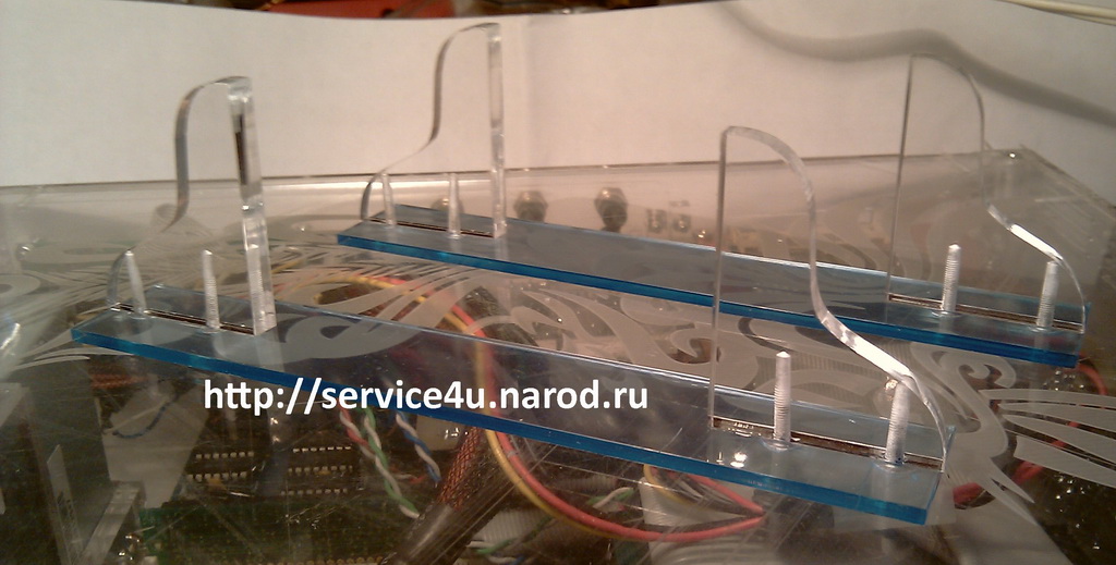
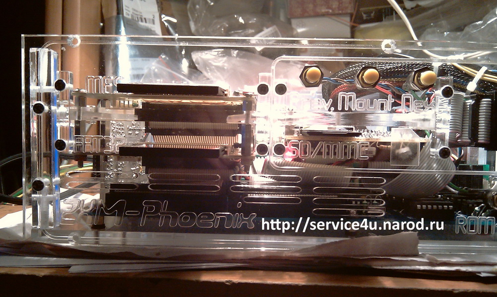
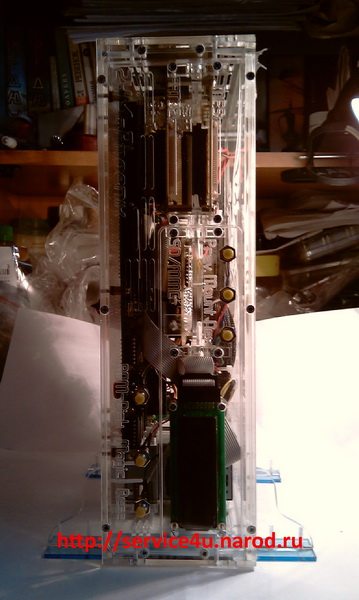
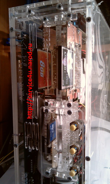
Next, assembly of holders for two CF adapters, a floppy drive emulator, a power supply and two stands for greater stability of the case in a vertical position.
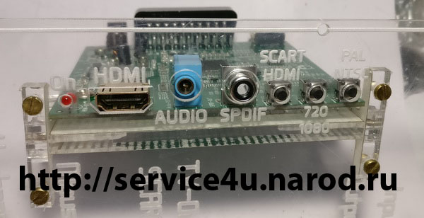
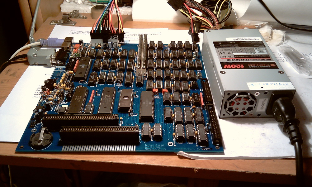
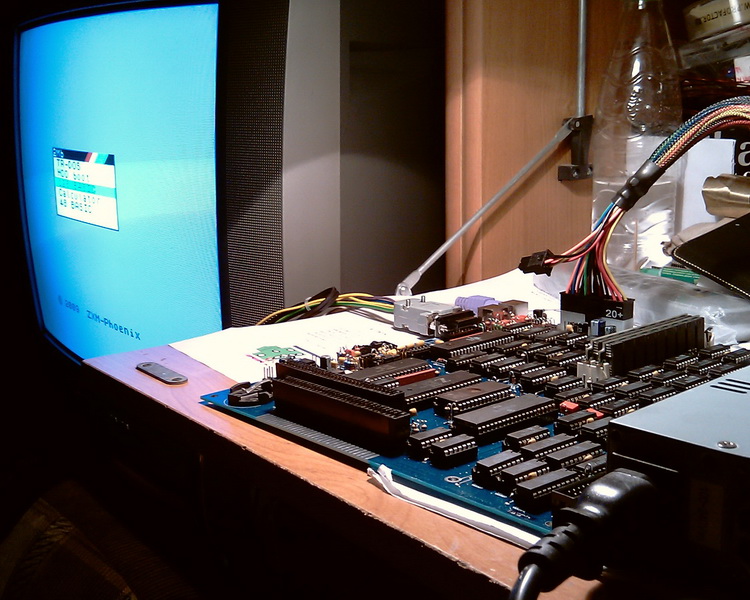
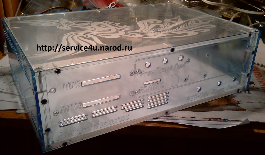
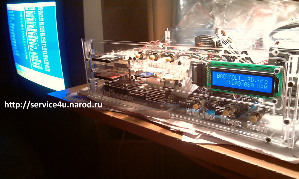
Test run after placing all the hardware inside. Final assembly and what happened in the end.
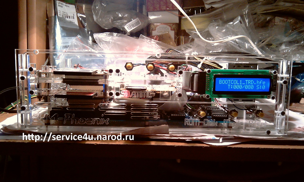

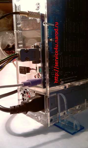
ZXM-Phoenix : : Final
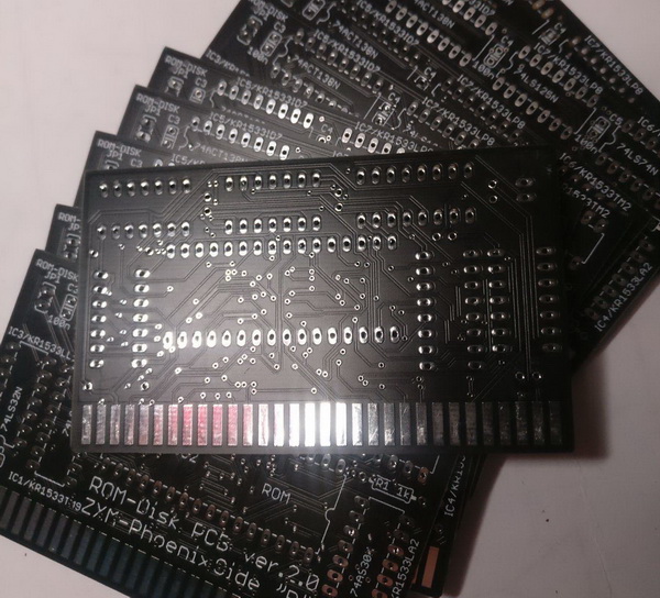
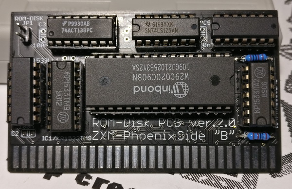
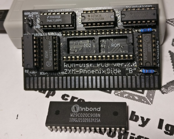
ROM-Disk Ver.2.0
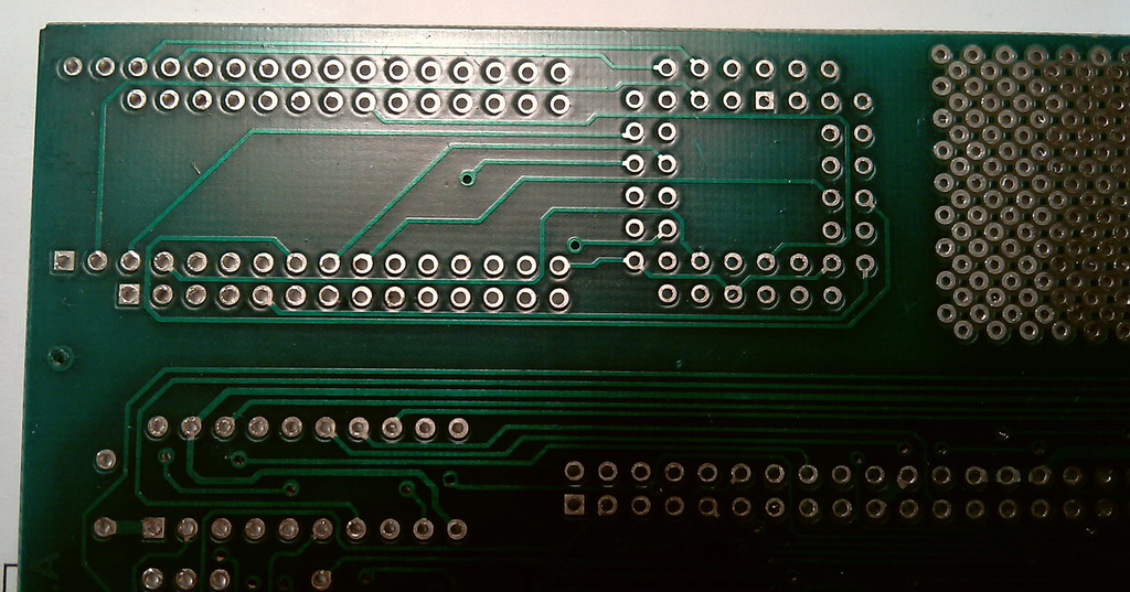
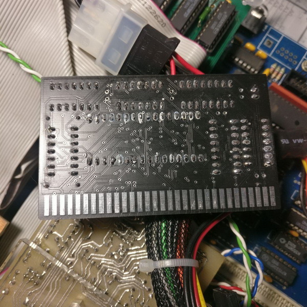
The ROM-Disk diagram is on this page above. She hasn't changed. I redrew the signet in Eagle and ordered it from the Chinese. With a black mask.
It turned out quite well. ROM-Disk can be used in computers equipped with ZX-BUS. The board is inserted into the ZX-BUS connector.
To date, the following computers are equipped with the ZX-BUS bus:
- KAY-256 Turbo (3 слота)
- Pentagon 1024SL (2 слота для v1.x, 3 слота для v2.x)
- Pentagon 2.666 (3 слота)
- PentEvo (2 слота)
- Scorpion ZS-256 Turbo+ (2 слота)
- ZXM-Phoenix (2 слота и краевой разъём)
- KAY-2010 (4 слота)
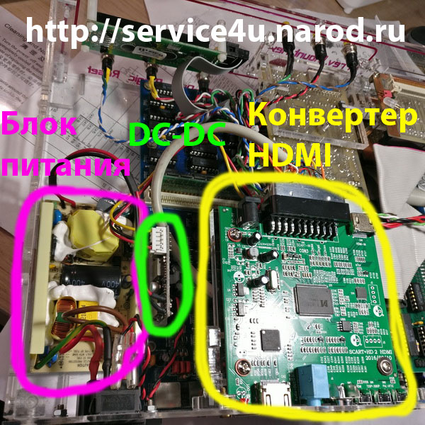
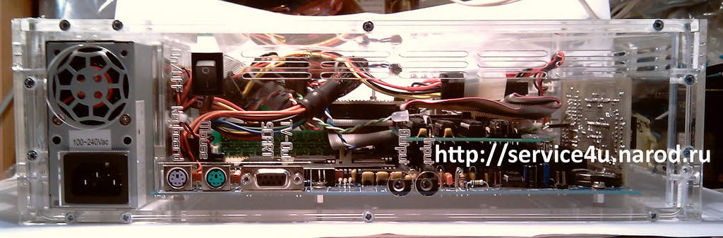
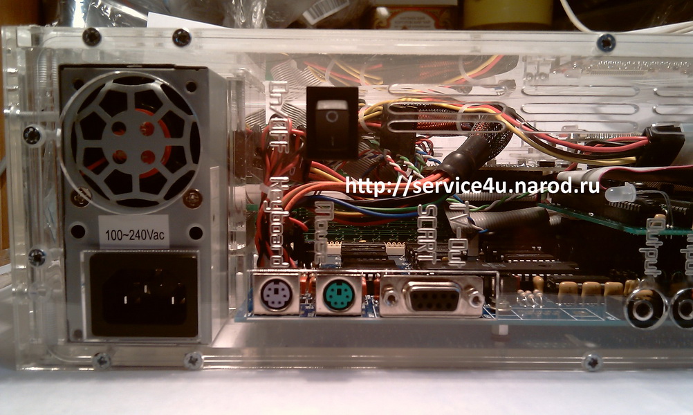
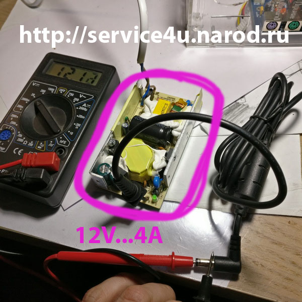
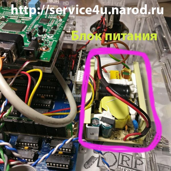
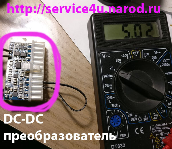
ZXM-Phoenix : : Power Supply
The usual ThermalTake ATX (heavy) 120W power supply has been replaced with a duo: a regular Motorola 12V/4A power supply and a DC-DC converter. This greatly lightened the weight.
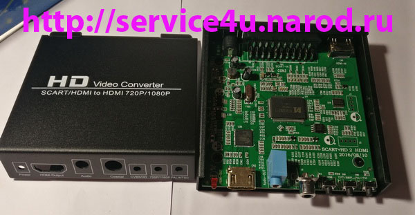
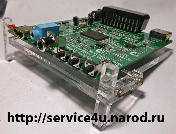
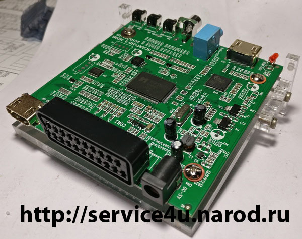
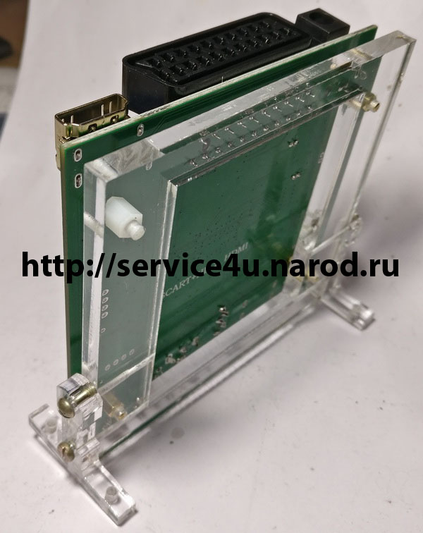
ZXM-Phoenix : : HDMI Converter
Left the RGB output, of course. Whatever the converter, but the analog connection gives a maximum of authenticity and the atmosphere of an irretrievably bygone time.