Power Amplifier WP2006 |
RU |
In 1993, when I study working course on various power amp modes of operation, the course supervisor offered me to pick up the full Power amp, which was produced as a kit, i.e. all the boards are soldered at once, along with a solid case and pwerfect heatsinks. The end user only had to connect all the wires (a detailed diagram was attached in the manual, as well as the ground wiring!!!) and configure it. But something did not work out for them, the output transistors were constantly on fire, they suffered at home with it in order - to no avail (and by that time that kit had been standing on the cabinet of my course supervisor for a year). That's why I was offered to pick it up and if something happens with it, I could keep it for myself. Within a week, I completely launched this amp, the problem there was in the failure of both channels and with current protection. I took it down then to a friend in the next entrance, he then had S50B (8 ohms), we listened to it, well, there was some sound, yes. But I was studying at that time, and I couldn't afford to buy more or less decent speakers from the Radio Engineering series for a scholarship, because the amplifier was mothballed. It was preserved until May 2009. I found only the terminal boards. The equalizer board along with the slider resistances is somewhere, but somehow it was not found.
I just wanted to build an POWER AMP, purely for myself, just to listen to music. I planned speakers from the "Radio Engineering" series, which is a legendary thread, such as S90, S50. It is so that the resistance of the speakers is 8 ohms. I went through the Internet at that time and saw a lot of diagrams. I stopped at Halton. On vegalab, I found a thread on discussing the terminal scheme for sub, not complicated, so I decided to collect it and listen to it, but in a wide band.
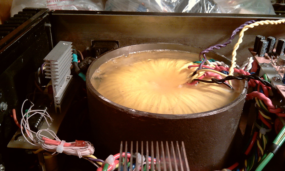
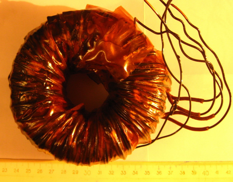
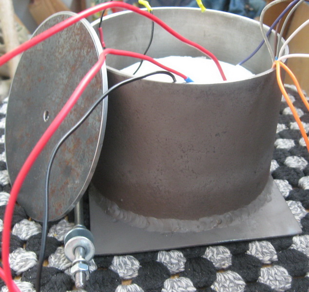
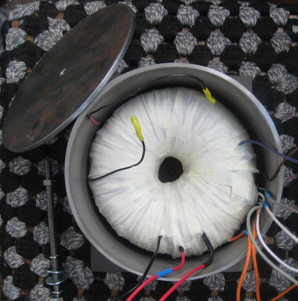
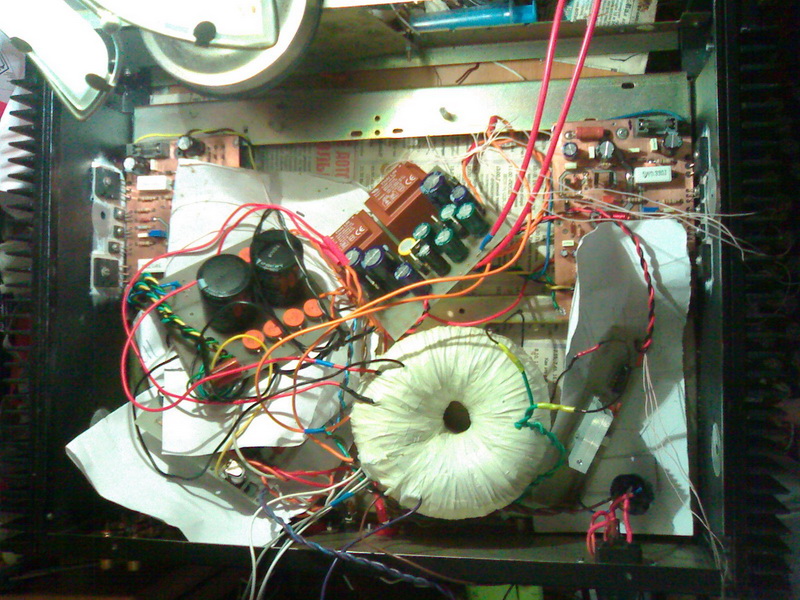
I won't go into too much detail on it, there's not much to discuss here. Soldered without errors and snot, the boards start up immediately, set the quiescent current, connect the speaker, listen. The feeder is almost classic-thor, secondary-two windings with a wire diameter of 1.32 mm in copper, two KD213A diode bridges, two capacities of 10000x63V, soft start, of course, protection with a delay in connecting speakers. Thor took this particular one because there is a lot of insolator. Secondary (2x12v, 1.52 mm wire in black lacquer) wound. The primary was wound up at the factory, which is good, but I didn't wind it up. Made a sarcophagus and steel pipes, the inner diameter of the sarcophagus is approximately 135mm. The wall thickness is 2 mm. I disabled it. In the photo, the trans is still not filled with anything. Just wound up the secondary, insulated and its done.
Well, in general, there is some sound. Compared to the TDA2050, this Holton doesn't sound any better. After going through various forums, it became clear that some special quality is not expected from Holton. Holton is generally imprisoned under the" open-air". There are Holton schemes and 750W per channel. Well, raise the voltage, but the outputs in parallel are bloopers and that's it.
Original "Junior"
Original "Junior"
Original "Junior" bottom
Holton almost
Holton pcb
Holton pcb

Holton pcb is done
power supply
Protection and soft start
Holton service
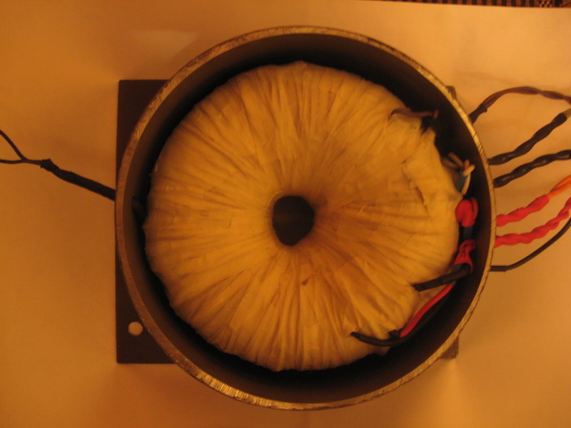
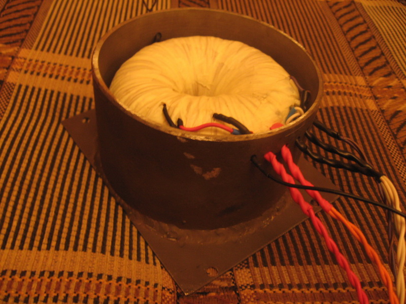
Thor
Thor
Thor
Thor
Thor/p>
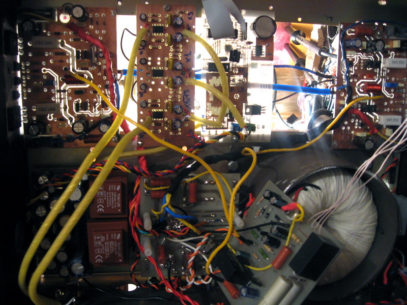
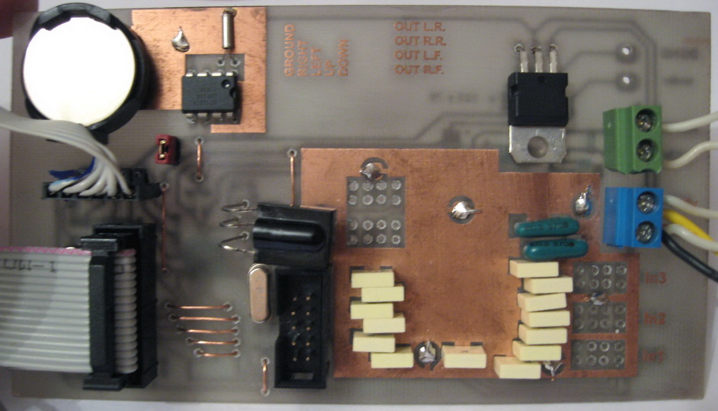
The photo below shows the buffer and tone block boards. The buffer circuit and board are below. A logical question arises: why are there 3 buffers? Answer: and I wanted to get a different gain for each input. And immediately ask another question: isn't it easier to make one buffer, put it in front of the MIND and adjust the Cu TDA7313, she has the opportunity to do this within small limits. Answer: at the very beginning it was so, but when you put a buffer in front of the amp, a very strong strong interference from trance is heard at the output, a kind of buzzing. If you move away from trance, the hindrance disappears or at least weakens. That's when I had the idea that I probably would have to rewind the trance. Or to leave the trance for SMPS. The SMPS was selected. Then 2 weeks passed, but nothing happened with the SMPS, I don't know why. But I'll come back to them later, after I finish my amp and before I start assembling the tube amp. Therefore, there are 3 buffers. And the interference is almost inaudible, but it is still there.
I listened to Holton in the stereo version, because one channel gives little idea of the sound of the device. You know, it resembles the sound of a car radio! Seriously! This is most likely because of 7313. In general, has anyone noticed how much music in the car is listened to like feces, rather than the same piece in normal areas, with good acoustics, with a good amplifier (at home). This is not our method. I want high-quality sound. We need to improve something somewhere somehow. Scratching behind the ear, it became clear that the Holton would have to be soldered, the torus would have to be rewound, and another one was needed with the volume control. Well, there is a work plan. I decided to start with the volume control. But first let's finish with Holton and some photos here.
Holton
Holton
Buffer
LCD and TDA7313 amp
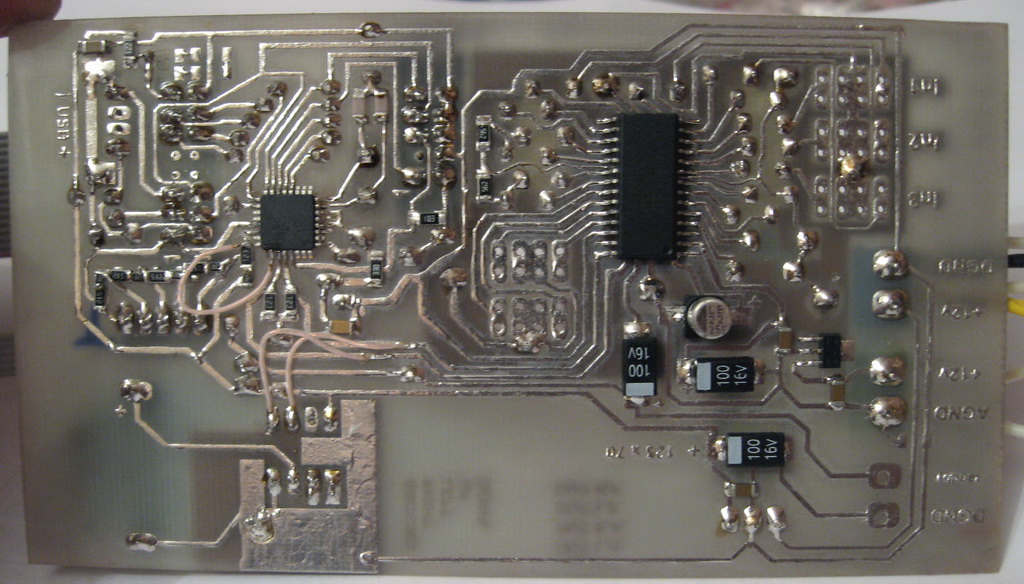
TDA7313 pcb. Top
TDA7313 pcb. Bottom
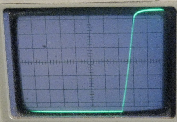
Slew rate
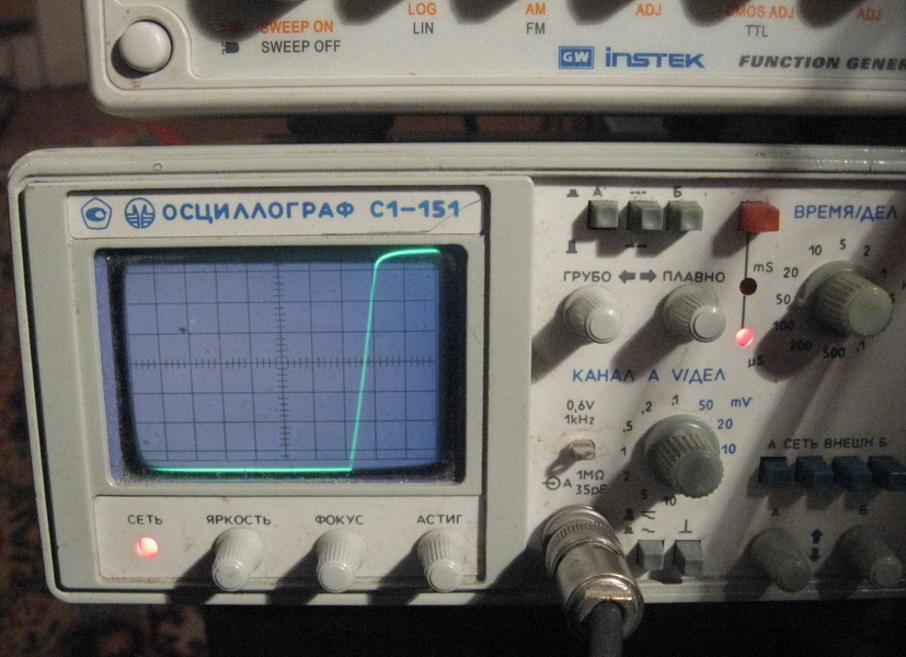
Slew rate closer
As a volume control, I decided to do something on PGA2310, there were several options. The first one is this. Another version of the volume control on PAG2310 was found here. The sources have been posted. I once taught basic at school, and even wrote one program for the school ZX-Spectrum. BASCOM downloaded. Let's go!
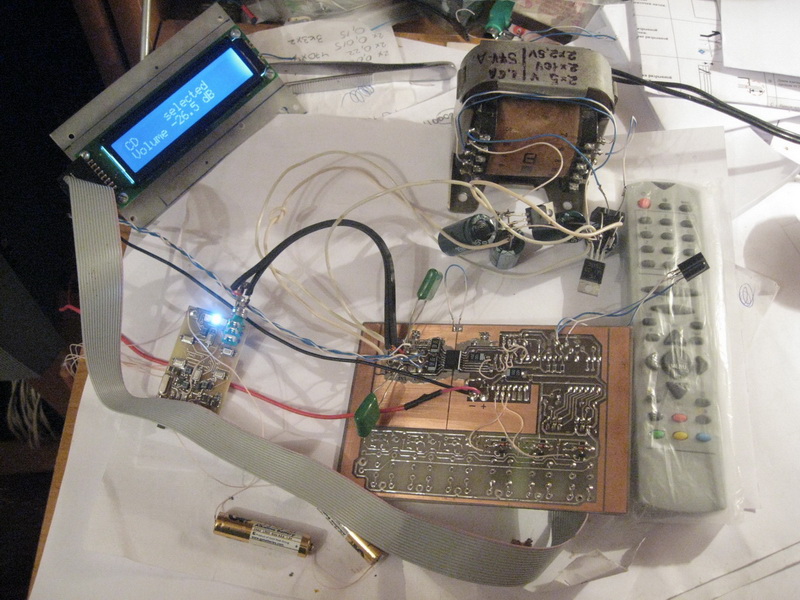
In the photo there is also the very first variation of the volume control. Just 1:1 according to the scheme and firmware. Because Holton was still present in the form of two channels, then the greeting on the LCD was Holton.
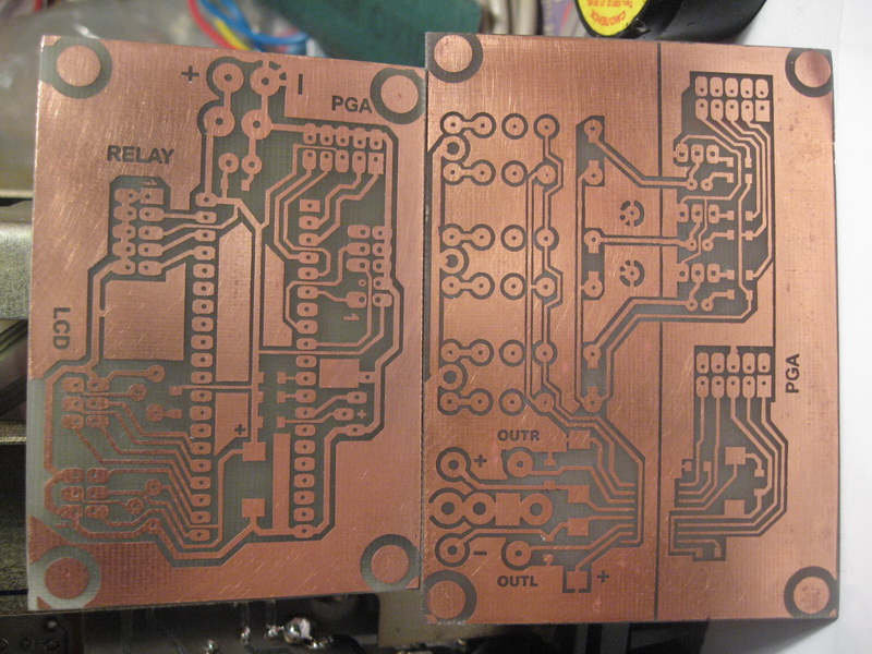
There is also a second version of the same regulator in the photo below. Why on separate boards? I decided to use tube here as well. I planned to fix these boards on the side walls of the tube board ground shield. So that's it.
PGA2313/Original
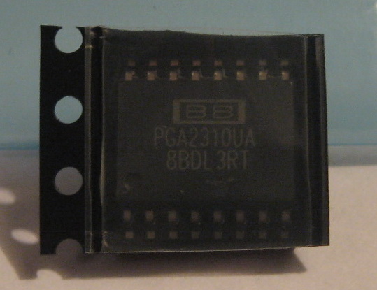
PGA2313
PGA2313
PGA2313
PGA2313
PGA2313
PGA2313
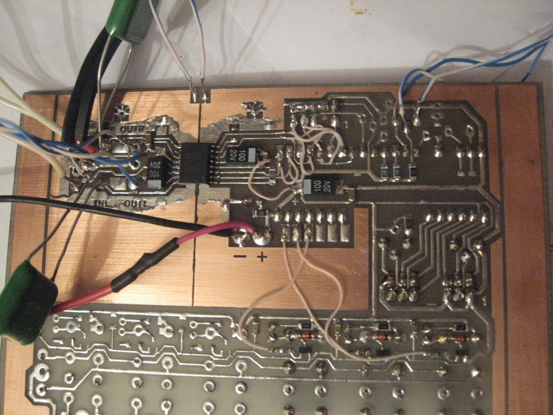
Analog
Digital
First run
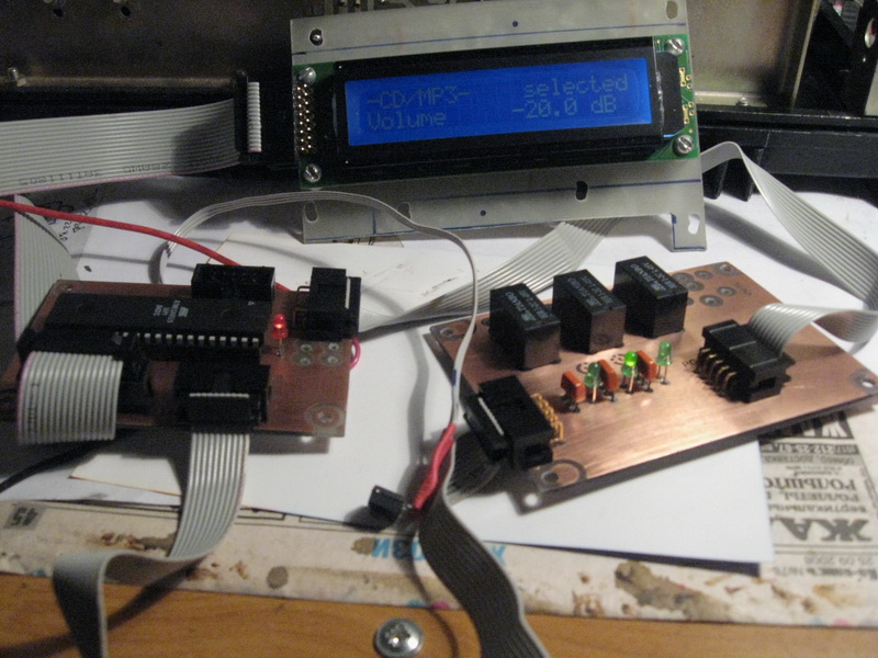
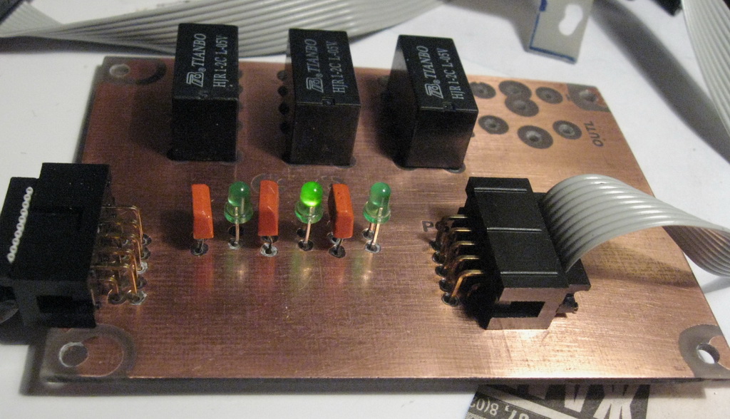
Green leds and KT315
LCD Printing

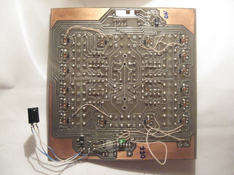
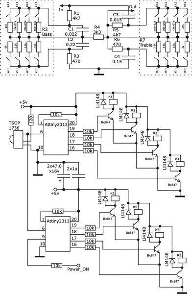
The device is absolutely working. Start ok after first power up. There are no problems. But there is a problem. Flat frequency response is good. But I like the low, so the timbre needs to be adjusted somehow. The standard Baskandal tone control was chosen as a test version. But I wanted to make it with IR control. Using volume control firmware, I made a code to control bass and treble switch relays, using ATtiny2313 2 pcs. purely for the convenience of wiring the board, one of them turned on and off the entire amplifier by IR. Later I rewrote it for the next version of the tone block. The sound is so-so. It resembles all Soviet technology tone constuction, in which such a tone regulator was used. HF sounds more or less, but the bass is bad. But it all resulted in an almost finished design. Let's go ahead. Putting together a timbre block. Next in the photo is a tone block and a tube voltage amplifier.
Tone control. Test
Tone control
Tone control
Tone control
Construction

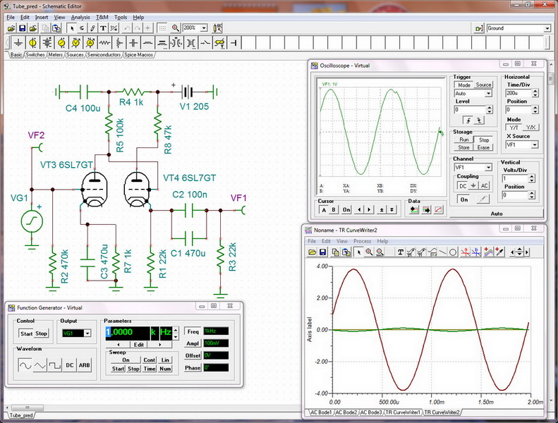
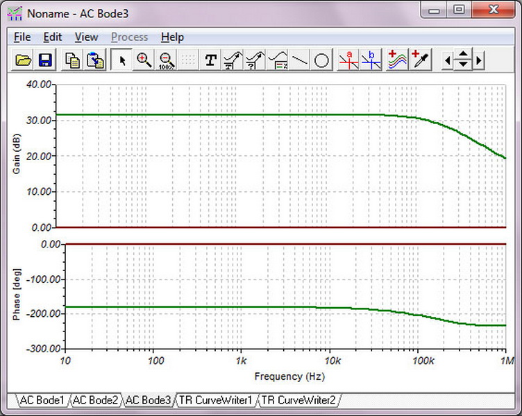
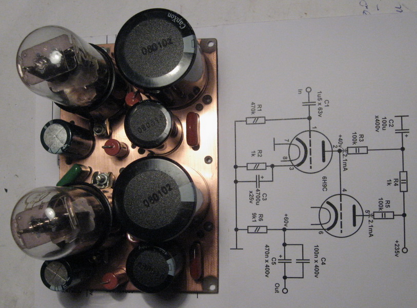
Tube amp.Schematic
Tube amp.
Tube testing
Tube testing
Tube power supply
Tube amp
Tube amp
Construction one more
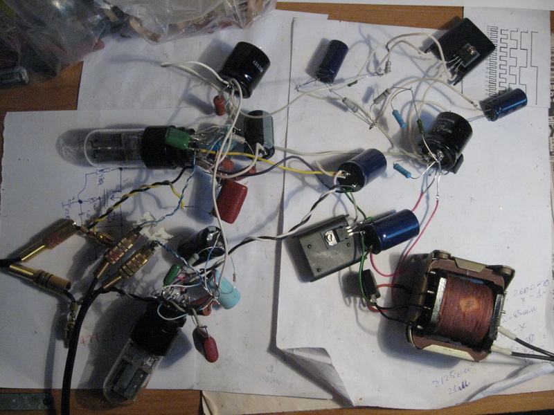
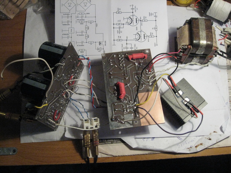
And if I should add tubes here, I thought, and still added. When connected to an external amplifier, it sounds somehow different from how everything transistor has sounded so far. There is something in this sound. Definitely there is!.. This was my first time hearing a tube sound. I listened to 6N8C and 6N9C, they have the same cap. After connecting all this economy to the path of its amplifier, it became clear that it would not be possible to get away from SMPS. We should at least try to rewind the thor. The tube catches any interference easily, and even amplifies it. So I made another small sarcophagus for tube boards. A ground shield was installed between the boards inside the sarcophagus. I just haven't screwed it down yet. I simulated the circuit on the lamps in the Tina program. I played around with resistors, capacitances. Everything is kind of super. The sarcophagus for lamps, in principle, did not solve anything. After all this, I realized it was time to end this circus and get down to business seriously.
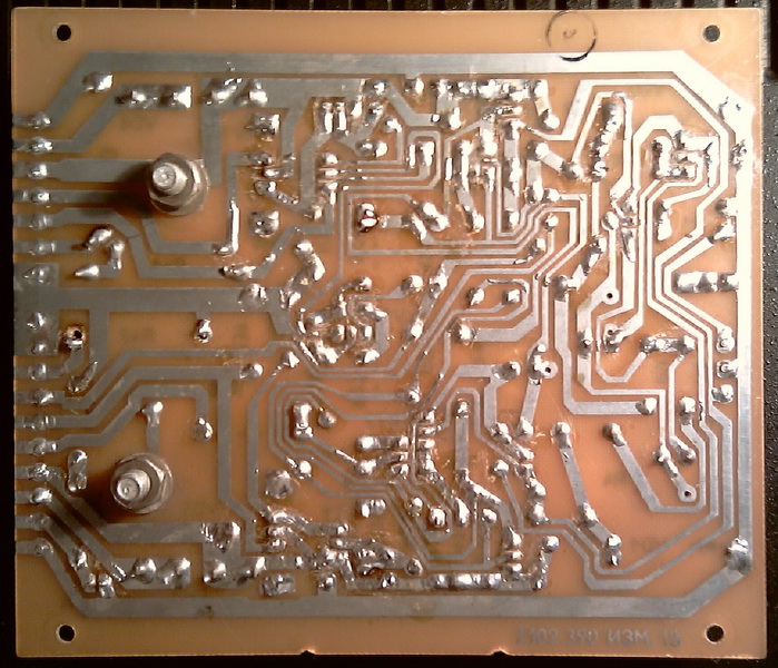
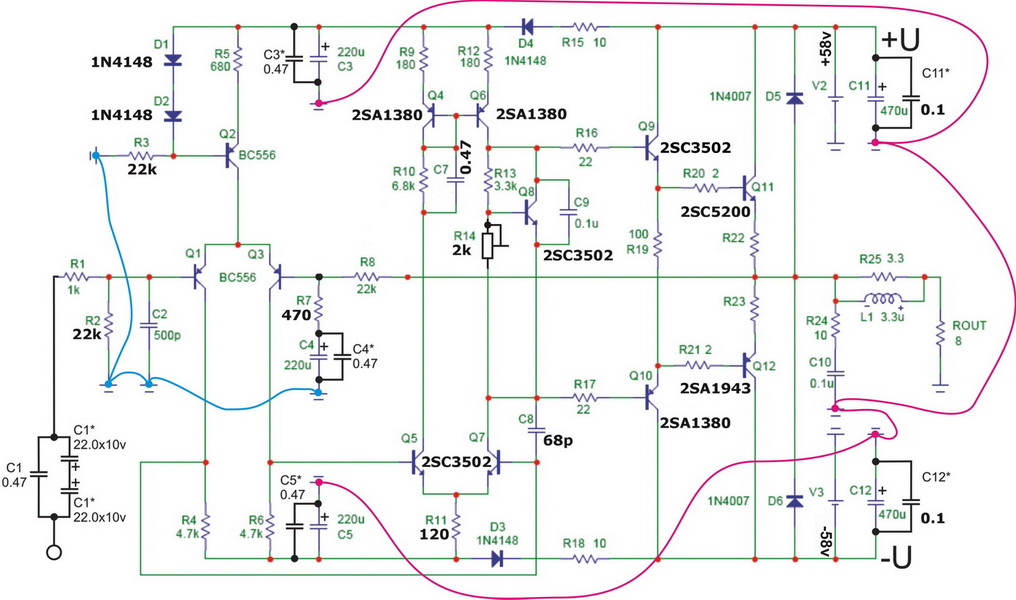
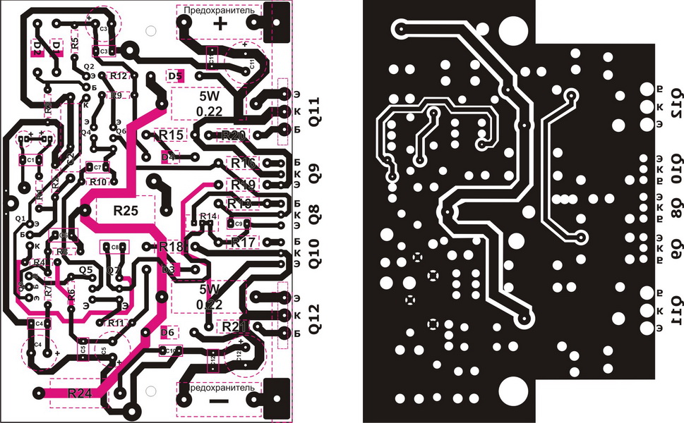
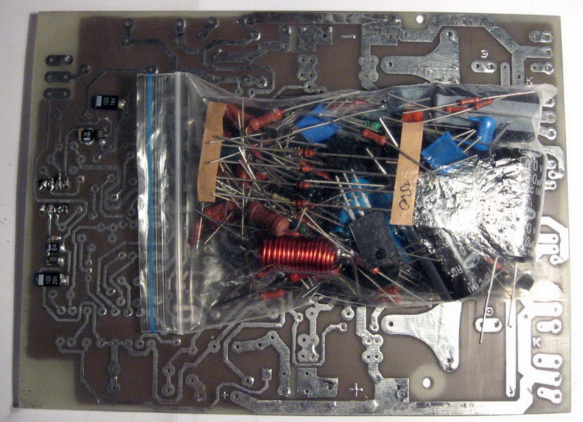
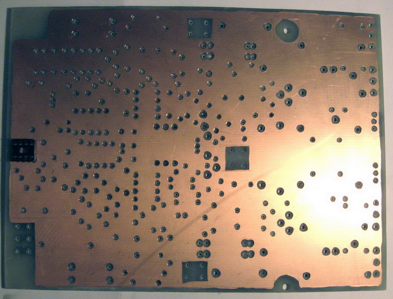
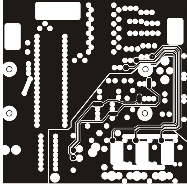
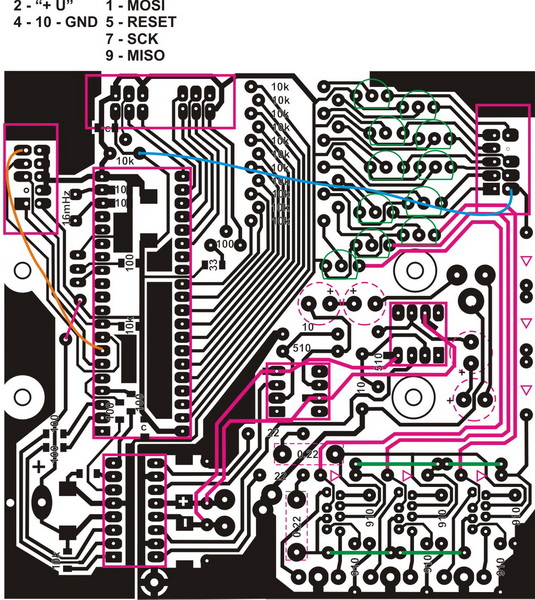
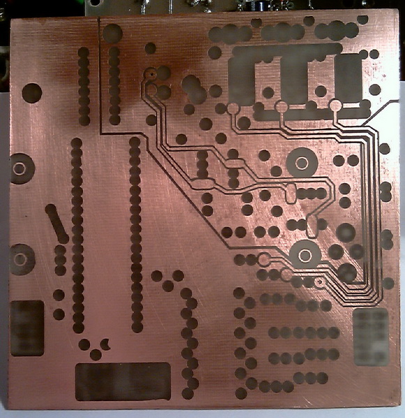
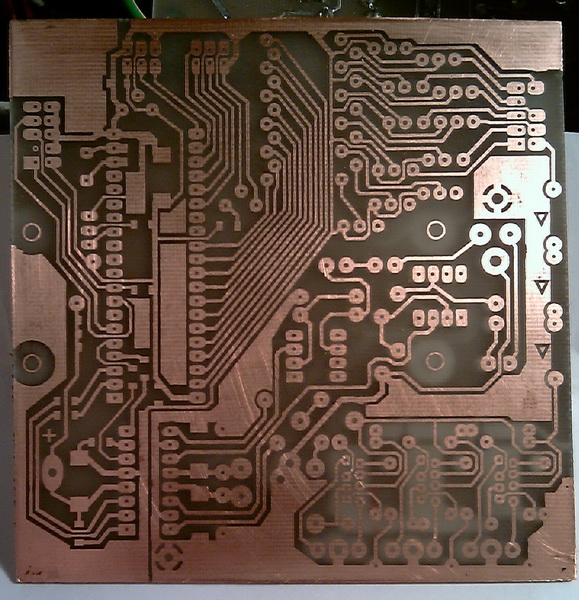
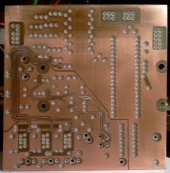
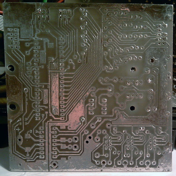
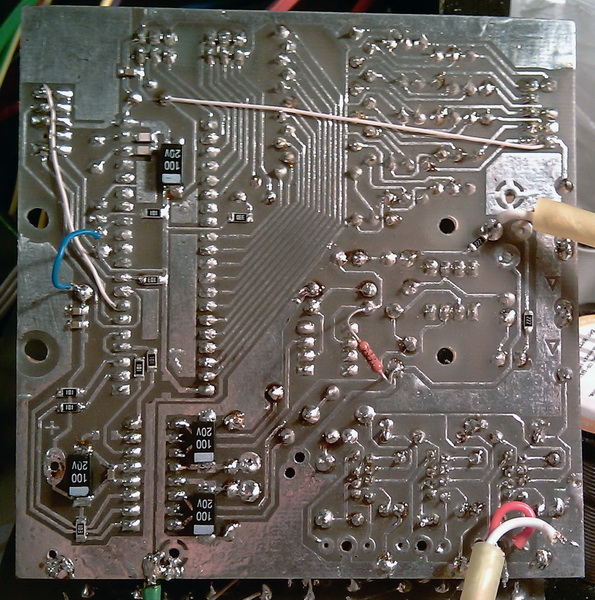
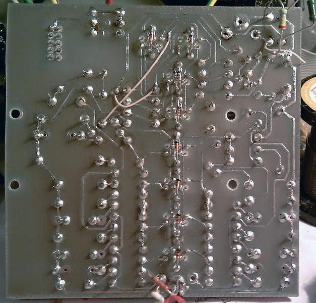
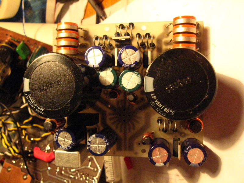
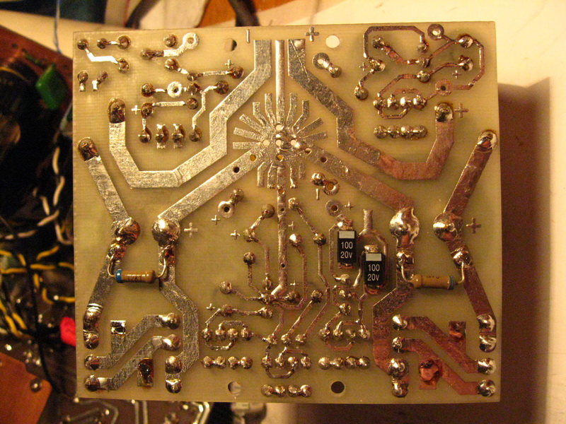
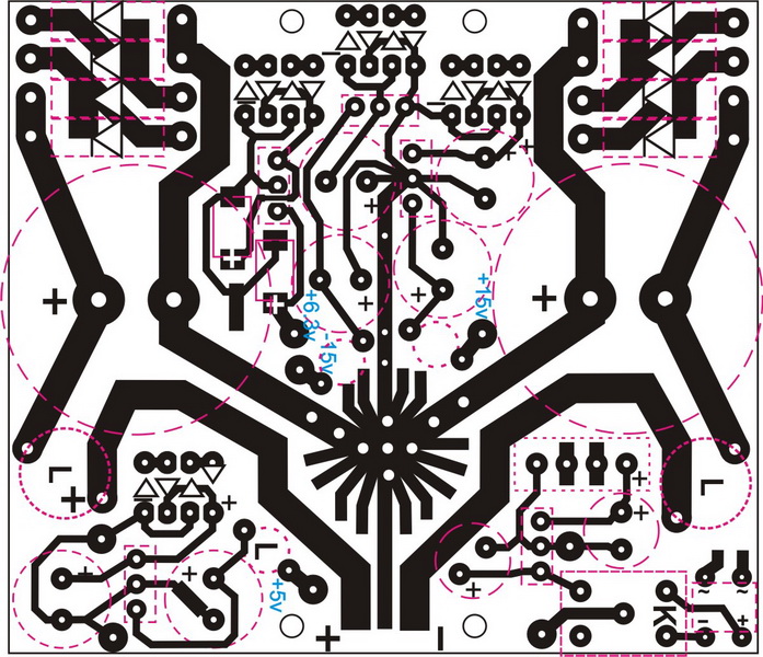
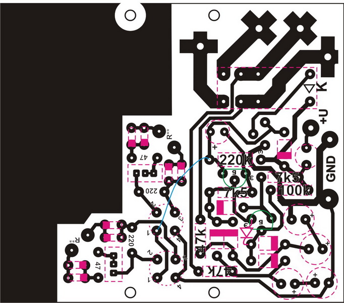
Vladimir Perepelkin's amplifier was chosen, WP2006 you know. After reading various branches on various forums, it became clear - they praise this amplifier for its quality, and this is what I'm looking for. The full version of WP was chosen for small things without wasting time. I made the board myself, as I usually do in CorelDRAW. I will not give a drawing of the first version of the board, it never worked as it should, some kind of bullshit with it was, it seems, connected with the incorrect arrangement of elements. Next, there was a second version of the WP board without current protection. Here it is.
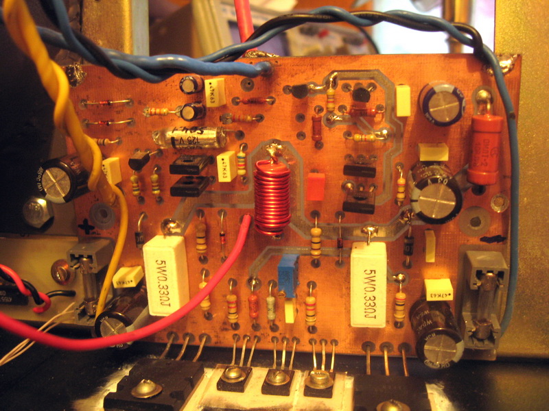
WP2006 PCB
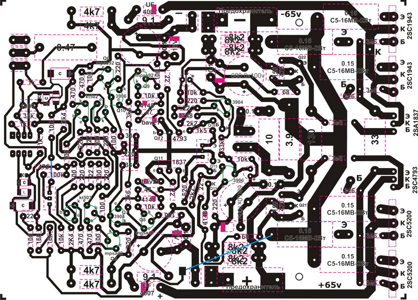
WP2006 PCB
WP2006 PCB
WP2006 PCB
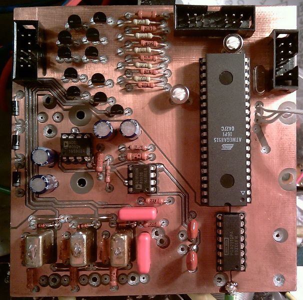
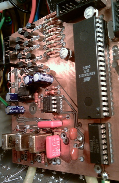
Inputs
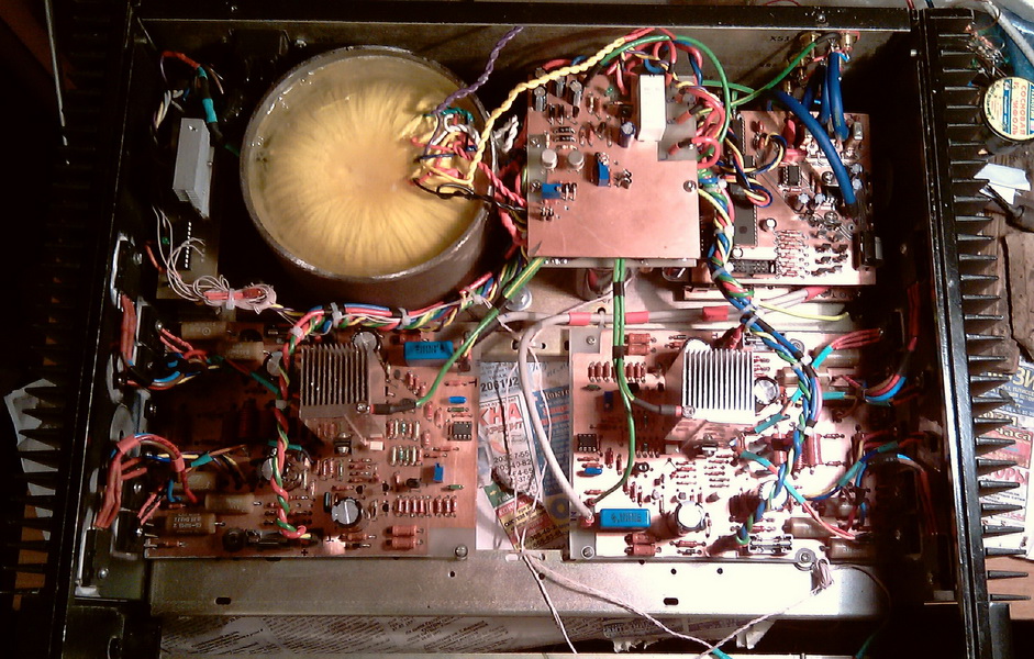
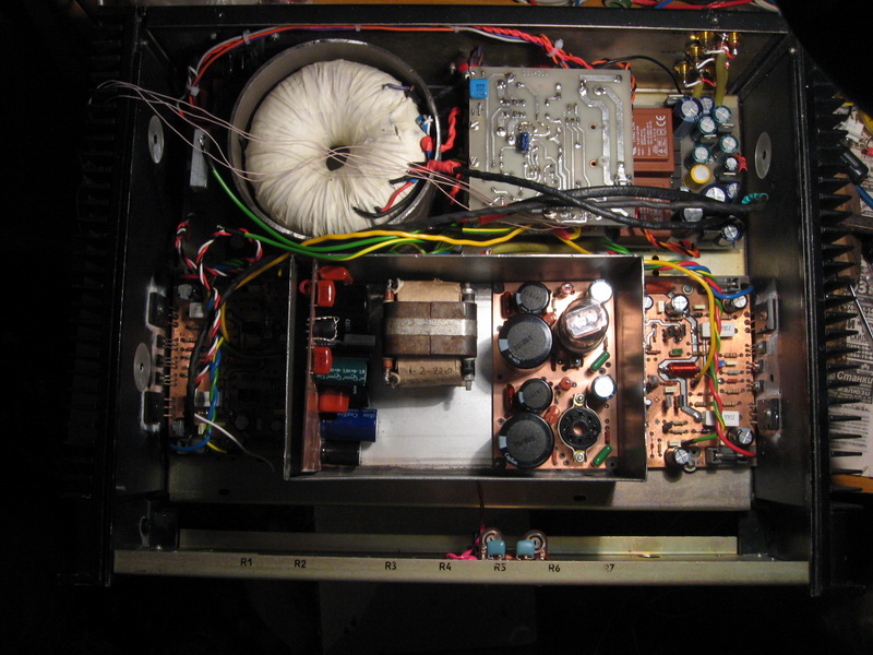
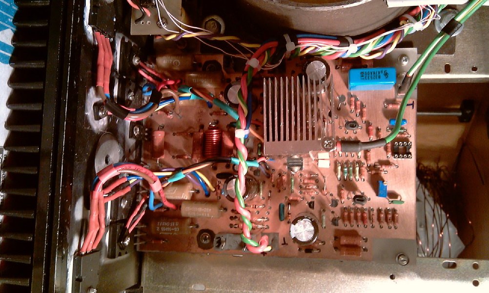
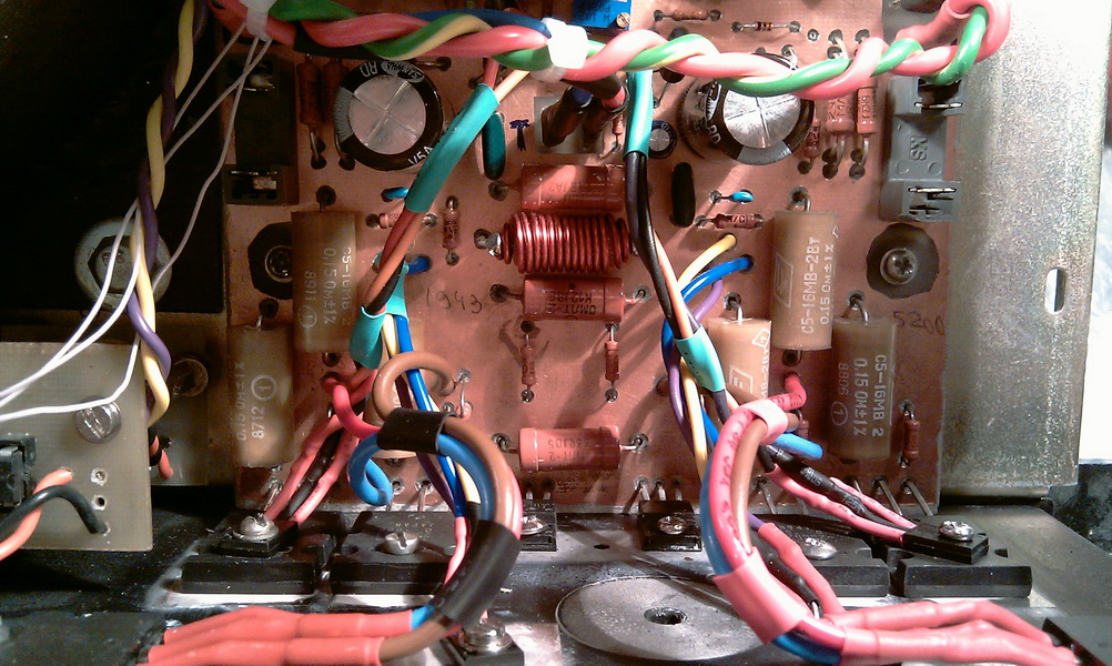
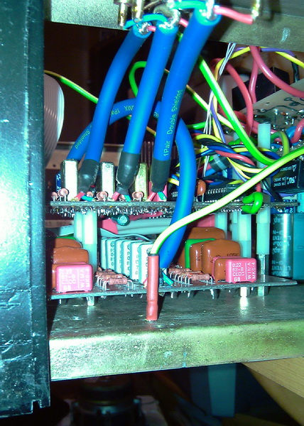
inside chassis
Inside
WP2006
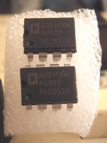
AD811_Original
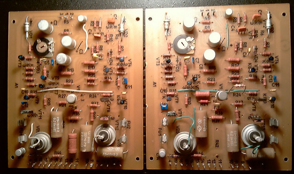
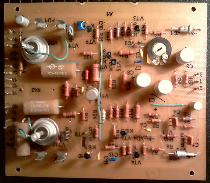
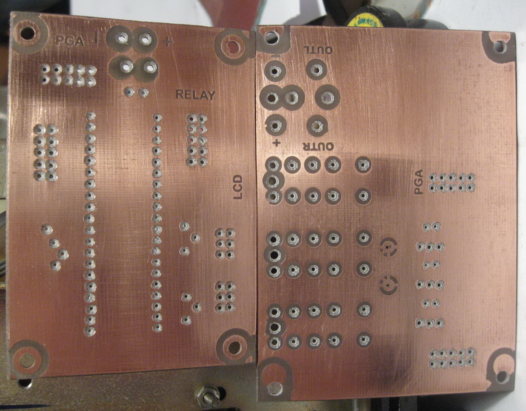
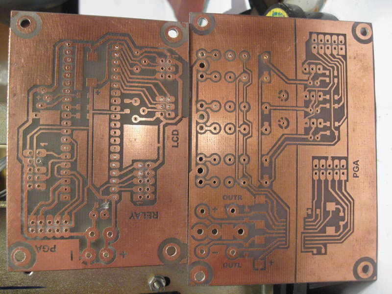
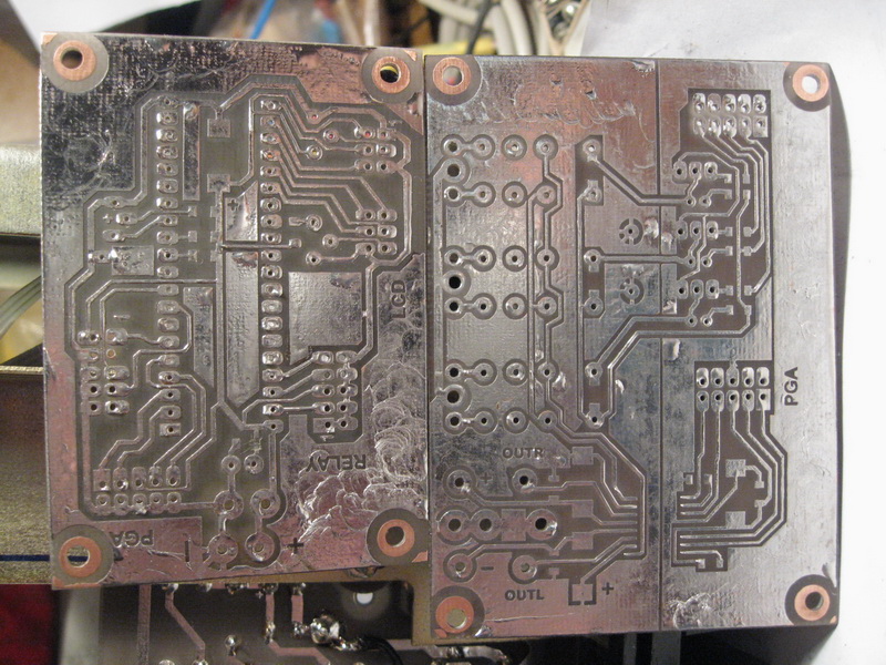
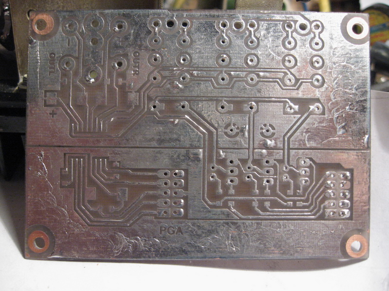
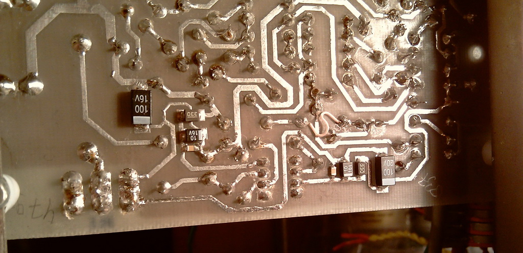
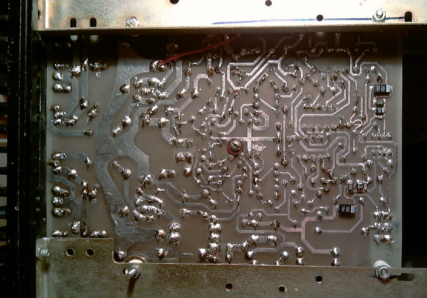
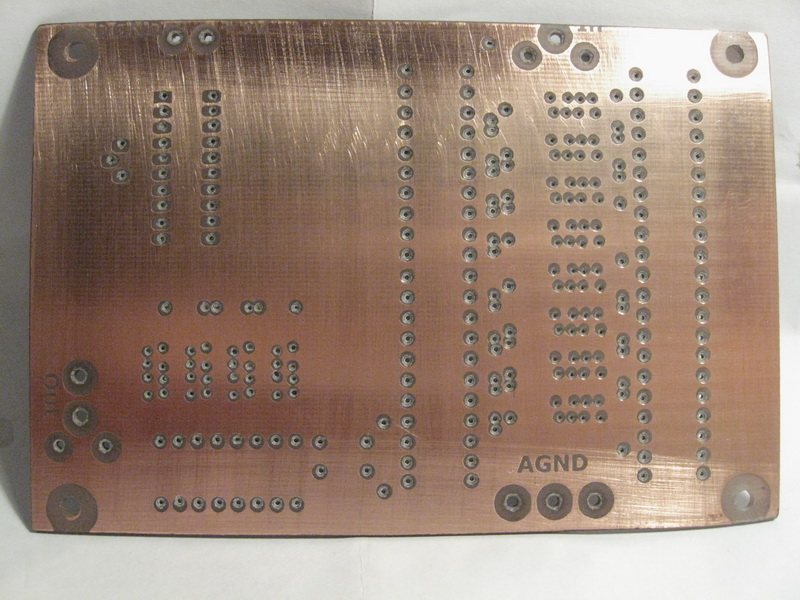
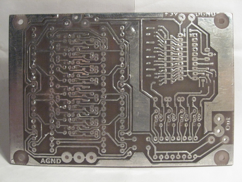
Before proceeding to WP, the thor was rewound (except primary). I launched the first channel in parts. First, the voltage amplifier. There were no problems. We give feedback to the voltage amplifier output. Everything is fine. Next, the current amplifier. There are no problems either. Everything worked. The amplifier pleased me. Everything is easy and simple. The second channel was soldered all at once. There were no problems. It started immediately. INPUT to the ground. We set the quiescent current. If there is one pair of output, we set about 80-100mA, for three pairs I set 280mA in both channels. We set the constant at the output 0mv. All operations should be carried out on a warmed-up amplifier, at least 15 minutes., just throw the input to the ground, turn it on without load and let it stand. I set the quiescent current by connecting the tester to the gap of the positive power supply wire of the amplifier. After setting the quiescent current, just in case, I turned on the tester in the gap of the negative power supply wire and found a run-up in the amount of 10mA. After selecting the resistances in the thermal compensation cascade, everything was displayed symmetrically and elegantly. The sound quality largely depends on the op-amp that you put on the input. So, we choose something above average lousy there. I will not pay attention much about the soldering, tuning and testing procedure here. There is enough info in internet to read. For those who want make my version of the board, the source of the seal in CorelDtrawX3 format is here. The board is fully operational. Soldered in the amount of two channels. Soldered without snot and shorties from obviously serviceable and tested parts before soldering starts immediately and without problems! I don't have any boards in sprintlayout format or in some other format, I draw all my boards in CorelDRAW. There are no deviations from the circuit, current protection is excluded, and that's all, actually.
Volume control
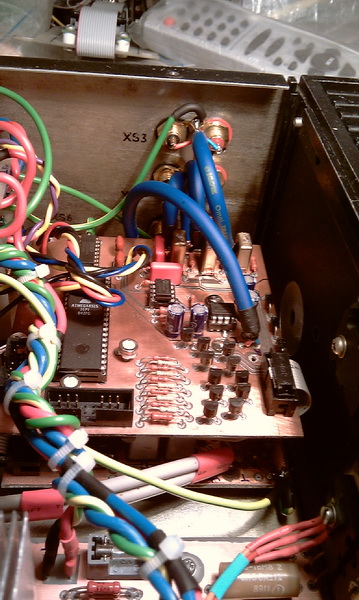
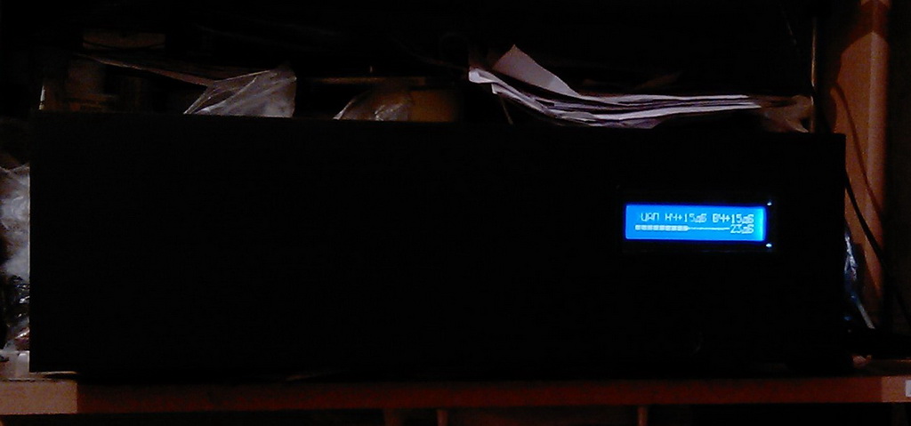
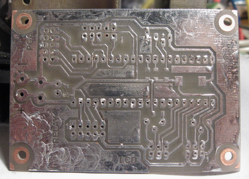
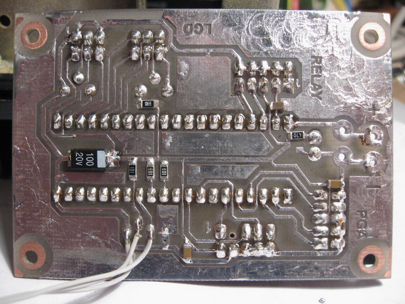
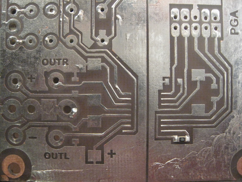
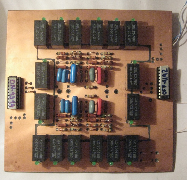
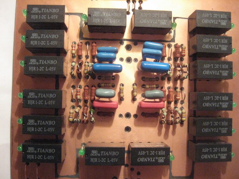
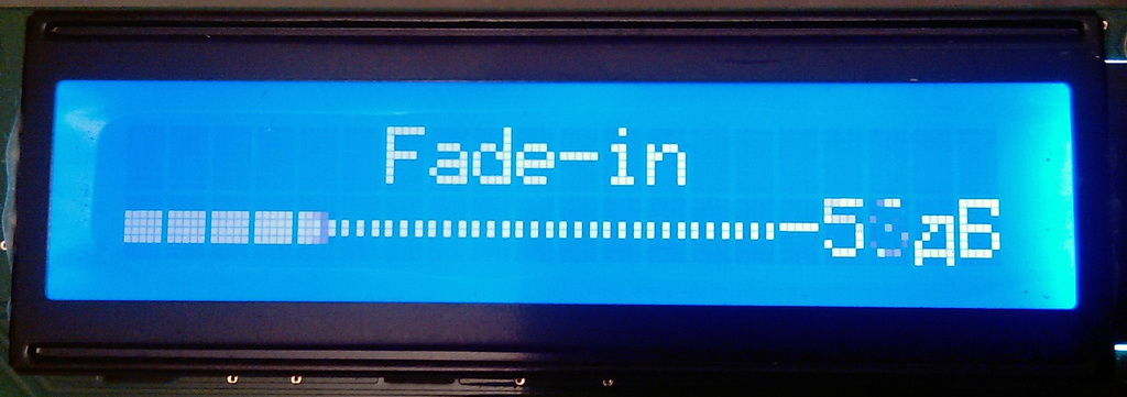
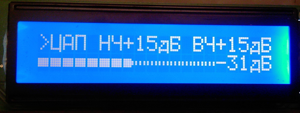
Danzup's firmware has been almost completely rewritten. In the author's original version, the volume control adjusts the volume according to the PGA2310 datasheet -95.5dB...+31.5dB, MUTE, input switching, button and encoder control, LCD backlight control, device on/off, and all this also via IR RC5. For buttons, you need to drill holes in the front panel, for the encoder too. I don't like to do it. Therefore, the control of the buttons and the encoder was discarded immediately and removed from the source code. I have 3 inputs, in the author's version - 6. In the author's version, the exit to MUTE was abrupt, and the exit from MUTE too. I added two modes: Fade-in - this is a smooth increase in the signal when exiting MUTE and after turning on the amplifier. Fade-out - a smooth decrease in the signal level when leaving the MUTE. For the translation of Fade-in and Fade-out, I did not pick up the words, so I left it everywhere, in English. I did the backlight control at the very last moment after everything, so in the photo the resistor, capacitance and transistor are soldered on top of the board. Plus, it didn't work for me right away. I tweaked the code a little and it worked. I also added one very important element of aesthetics - a sausage (bargraph) in the bottom line of the LCD. Appears when adjusting the volume, in Fade-in and Fade-out modes. After, I added a read/write to the EEPROM. The volume values and the selected input are written to the EEPROM. If the selected input has not been changed (it is compared with the one written), then its value is not overwritten (this way we will save the EEPROM resource a little). After that, the procedure for identifying the RC5 IR remote control and adding commands from the recognized remote control was added, i.e. training mode (the author of the original piece of code for adding commands is FarmTech (Kim) with forum, I just screwed this piece of code to the firmware and slightly corrected and expanded it). After that, I added another high-speed volume control. Those. we can actually adjust the volume with 4 buttons: one pair of buttons is slow +/-, the second pair of buttons is fast ++/--. The volume in this knob is adjusted as follows: from -95.5dB to -53dB, the volume change interval is 2.5dB, with a further increase in the volume level up to +31.5dB, the speed drops to 0.5dB. When the volume is changed with the additional two buttons, the adjustment speed changes as follows: from -95.5dB to -53dB, the volume change interval is 10dB, with a further increase in the volume level up to +31.5dB, the speed drops to 5dB. I also added passive preamp control to the ATmega8515, purely jerking relays, namely independent switching of high and low frequencies from "0dB" to "+15dB" with an interval of 5dB. Those. 0, +5, +10, +15 for bass and treble. About preamp later. Let's finish with the volume control. Now boards and photos.
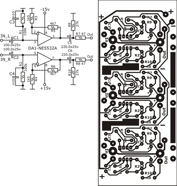
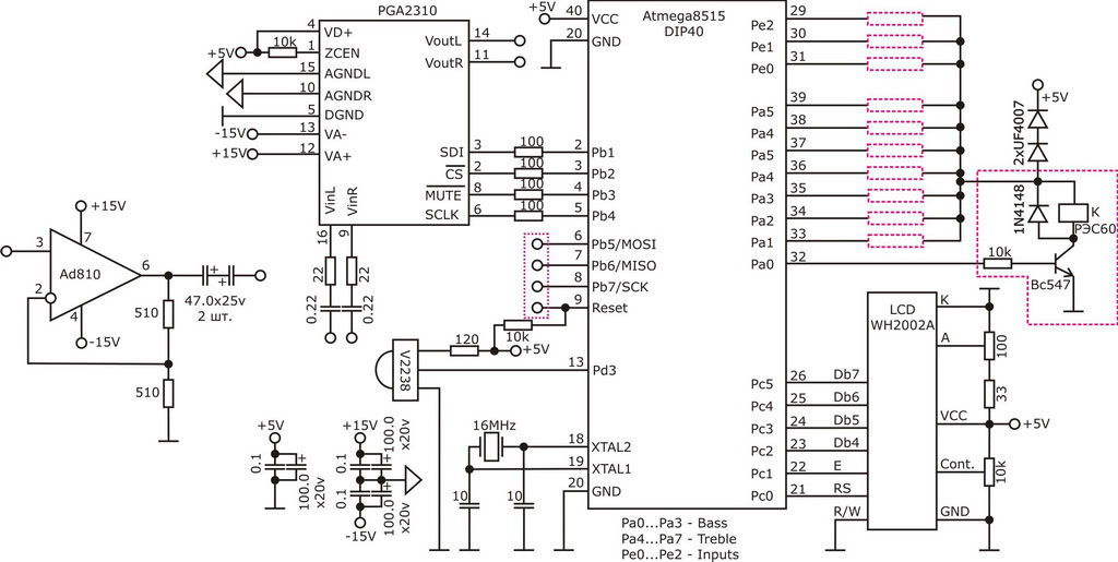
VC Schematic
VC PCB
VC PCB
VC PCB
VC PCB
VC PCB
VC PCB
VC PCB
VC PCB
VC PCB
VC PCB
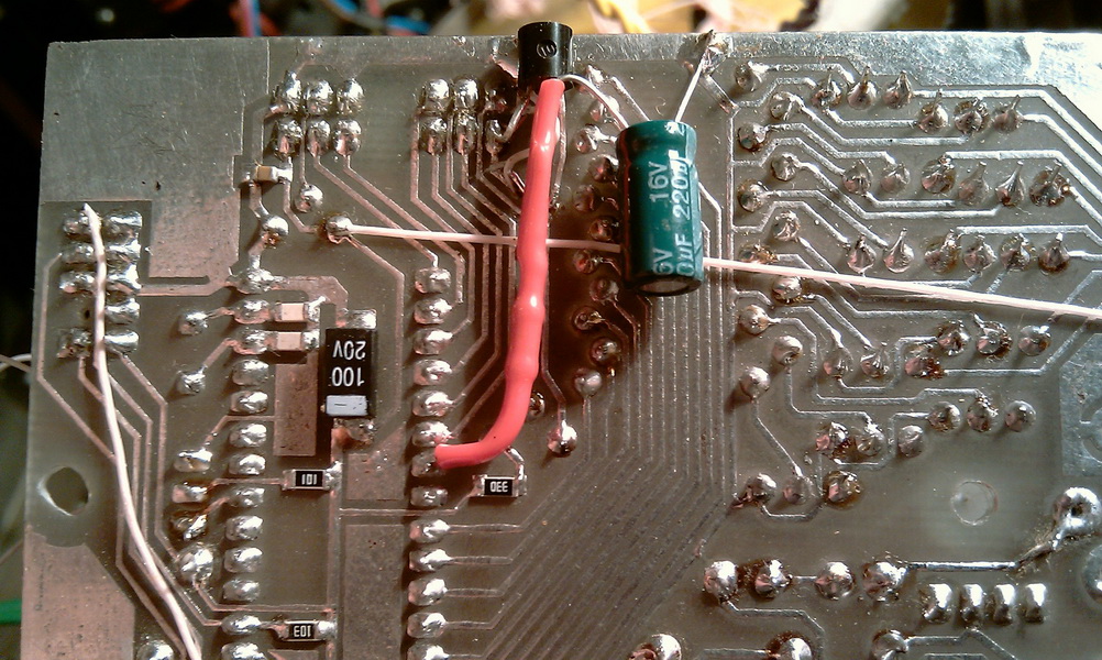
Unused inputs are pulled to ground through 910 ohms. For all supply voltages (+5V, +/-15V) there are LC filters. IR remote control - simple, RC5, from Samsung TV, with code page address "0". You can use any RC5 standard IR remote control with a different code page.
How it works
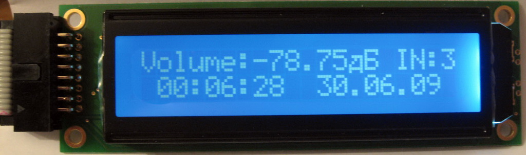
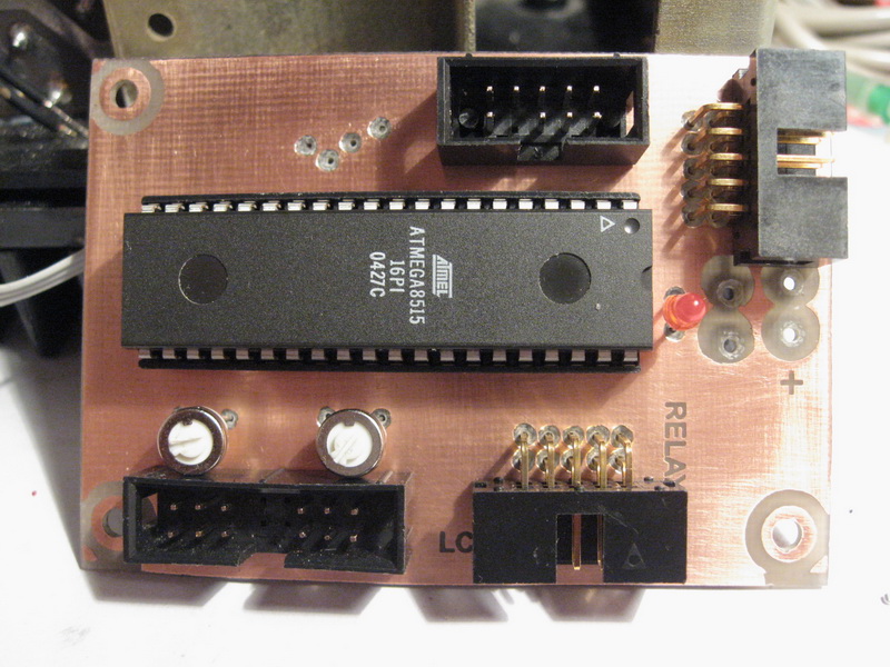
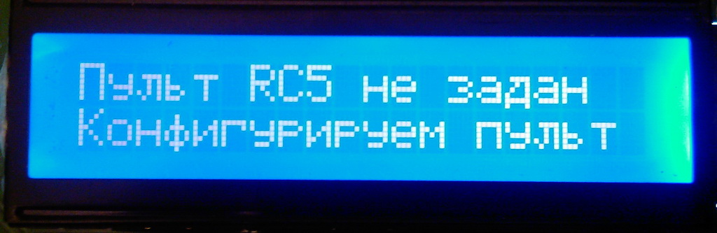
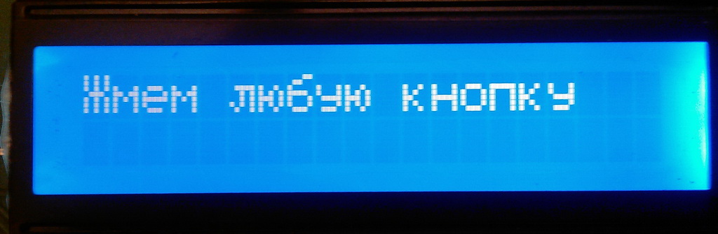
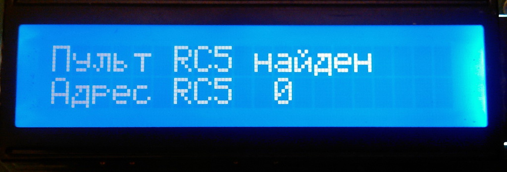
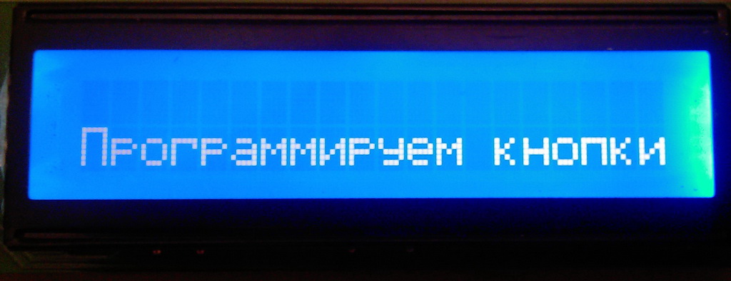
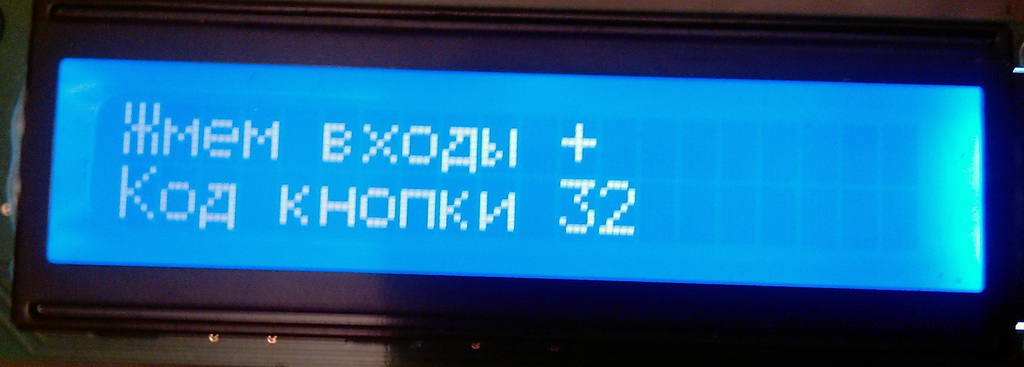
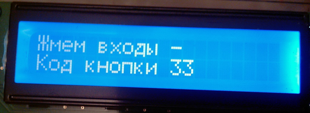
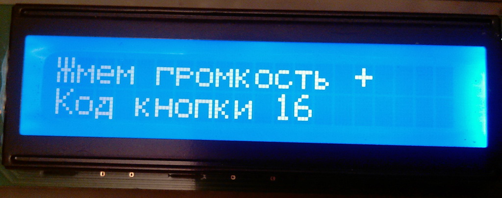
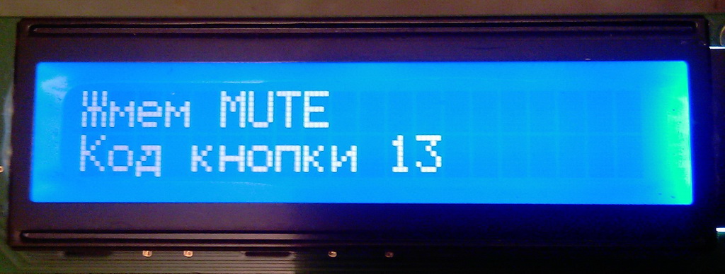
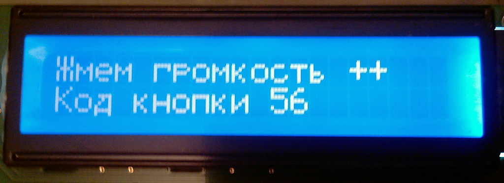
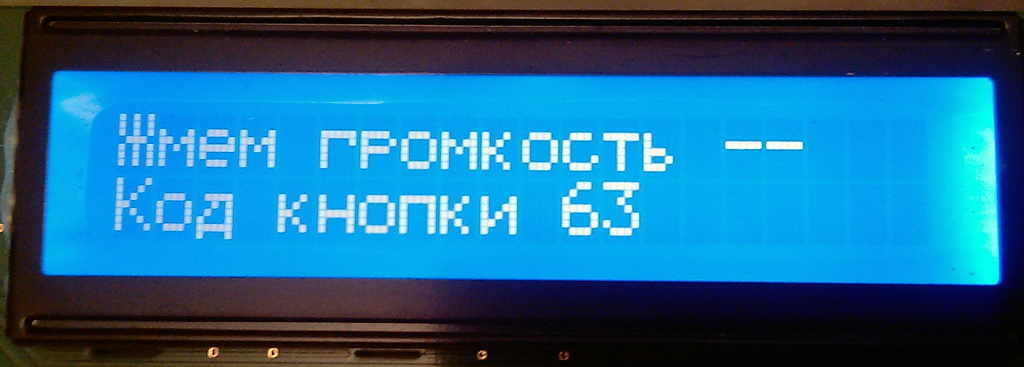
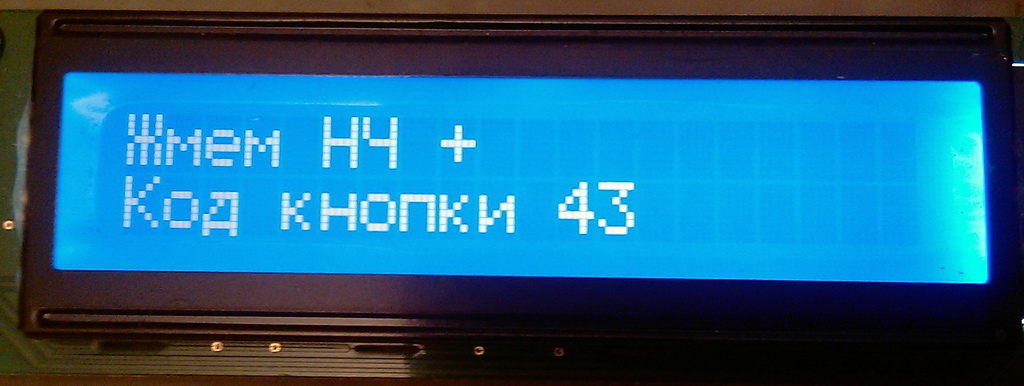
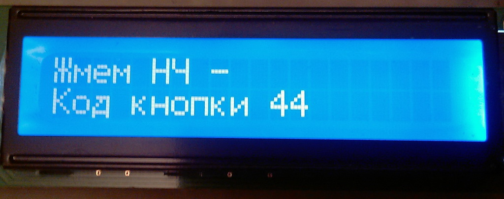
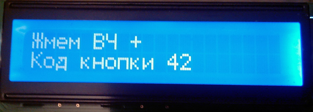
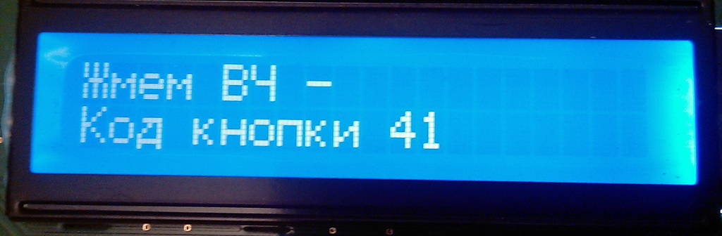
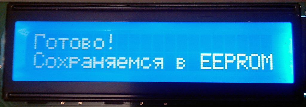
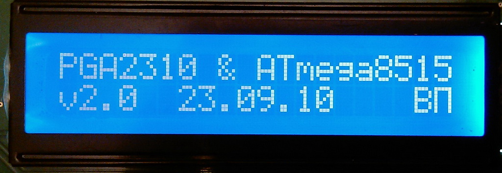
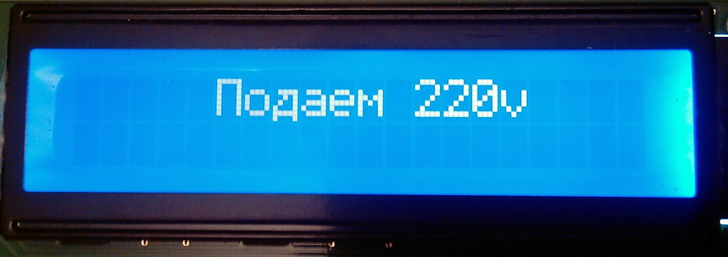
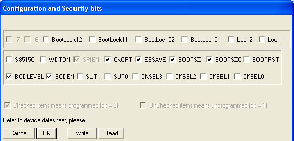
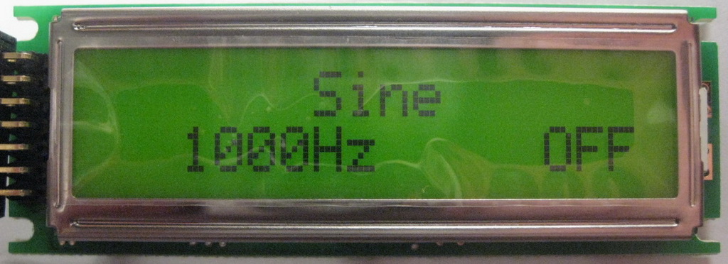
We take the MK (ATmega8515, DIP40), erase the whole if this option is not provided by the programmer interface - erase before flashing. Flashing MK. We sew two files - *.eep in EEPROM and *.hex in flash. We put the fuses on an external quartz, the frequency of the quartz is 16MHz, bodlevel 4.0v, EESAVE (so that the EEPROM is not overwritten when changing the firmware), the rest can not be touched. We insert the MK into the soldered device. PGA2310 does not need to be inserted and +/-15V power supply is not necessary, we just check only the digital part first. Turn on (serve + 5V). The code page address of the IR remote control is read from EEPROM. If there is something different from FF in a certain EEPROM cell, then the configuration of the IR remote control is skipped and the MK proceeds to the main program: the command codes for the buttons on the remote control, the volume, the number of the input selected before turning off are read from the EEPROM. Next, a splash screen with the version and date of the firmware. At this time, the soft start works. Further, after 4 seconds. - the second screen saver "We supply 220V", at this time the soft start relay clicks, closes the damping resistances with contacts, and there is a delay in connecting the speakers to the amplifier output. Another 5 seconds later. speakers are connected, in the main program loop the PGA2310 exits MUTE and then Fade-in is performed, after which a signal appears at the PGA2310 output. It appears immediately after the start of the Fade-in, and becomes audible as the signal level rises. The indicator displays the current volume level in the form of a Bargraph (sausage) and in "dB" in the bottom line, the top line displays the selected input, the state of the relay switch for bass and treble. If you do not press the buttons on the remote control for a certain period of time, the backlight turns off (however, we save not energy consumption, of course, but the backlight resource. In my WH2002A indicator, it is 10,000 hours). If, after power-up, FF is read in a certain EEPROM cell as the address of the code page of the IR remote control commands, then the program proceeds to configuring the IR remote control. What and why should be pressed is displayed on the screen. You just need to do what the program requires of you and everything will be OK. I think the photos will tell everything else that I'm too lazy to write about, and it will become clearer what's what.
Fuses
: : Firmware : :
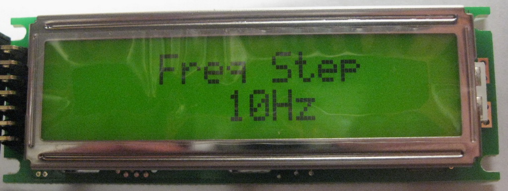
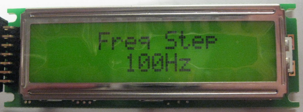
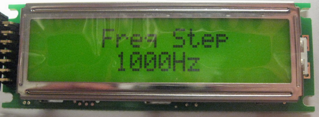
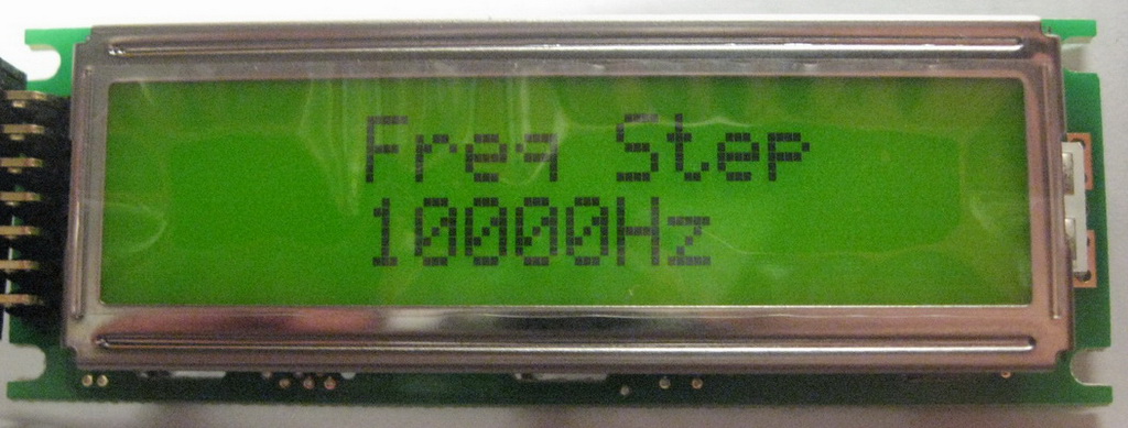
I forgot one more thing: the IR remote control can be reconfigured forcibly. To do this, before switching on, short to ground the 1st output of M8515. After that, we supply power and immediately get into the procedure for configuring the IR remote control. In this case, the 1st output of the M8515 can be released from the ground. In the final version of Bargraph, I made an effort and changed the method of filling the character space, dividing it into 5 parts, because there are 5 points in width. Made unfilled characters with sparser strokes.
In the final version of Bargraph, I made an effort and changed the method of filling the character space, dividing it into 5 parts, because there are 5 points in width. Made unfilled characters with sparser strokes. It doesn't look bad, it fills smoothly.
At forum people are very friendly, willingly share pieces of code. From the latest news, I will say that it is possible to add such options to the firmware as: editing the output text on the LCD and Vu Meter with the output of signal levels on the LCD. But all this is not on this chip - ATmega8515 is not enough for this, now the chip is 95% occupied. The benefits of Vu Meter are very doubtful, I'd rather save the backlight than look at the twitching rectangles. It is possible to carve out some places by transferring text to EEPROM, but this is not good, because EEPROM has a write resource of 100,000 cycles. Therefore, only the transition to ATmega16/32 is ahead. But what I have is more than enough.
Tonecontrol
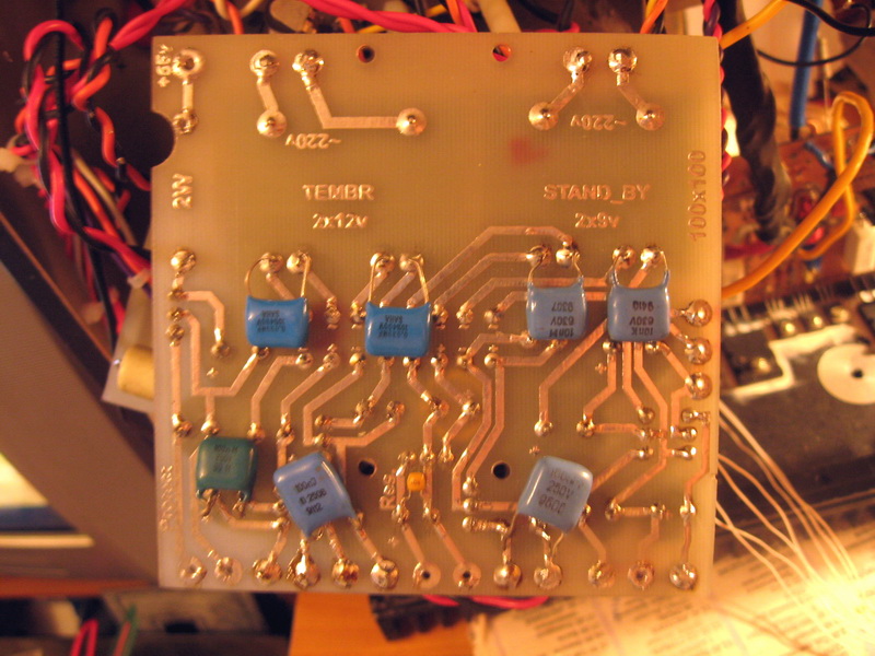
One of the tone block options is located higher on the page. Later I made another version of the tone block. Scheme borrowed from Danzup from the same forum and all from the same same branches. I put the plug for Tanya2313 myself, nothing complicated, just jerking ports.
Compared to the previous version, where Tanya2313 is present in the form of two independent individuals, a hefty board and half a bucket of Chinese Tianbo relays, everything is compact here, the RES60 relay (Made in the USSR - how long have I not written this combination of letters, however). And the sound is about the same. Slightly improved it by selecting resistors and capacitances. The circuit was pumped and was not soldered, but lies in a bag and a box, I just left it, not for something, just like that, although I didn’t really like the sound, mediocre, very mediocre ... The firmware is here here. The button codes are fixed, there is no learning mode for the IR remote control. Whoever needs it can reassign the buttons himself or something else - it's not that complicated - BASCOM.
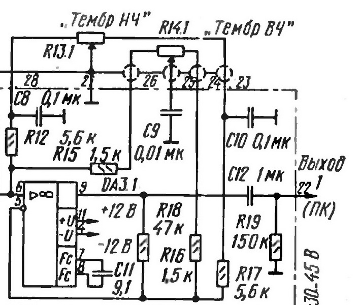
I will also write about what happened next. Further, Sukhov is. I think everyone remembers that scheme from the Radio magazine. Well, for that time it was not very bad. Yes, K157UD2. Absolutely normal opera. I do not argue. Normal for 1991. Definitely. Simply, then there was nothing more to solder on. Yes, and those were not very easy to get. And, there were also K (R) 574UD1A, B - the most gorgeous opera. Output signal slew rate 50V/µs. I remember that at that time I had to solder a playback amplifier - I ran after these UD2s, yes, but I found it. But the 574th series was more accessible ... Well, yes, all this is lyrics. To the point - look at the slides.
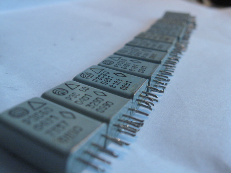
RES 60. Straight from the USSR
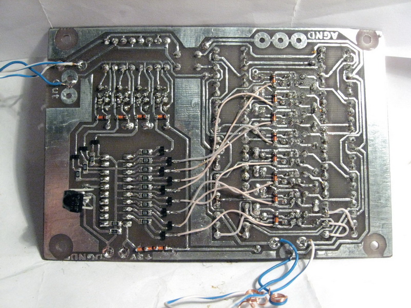
Another version. Bottom. Sealed
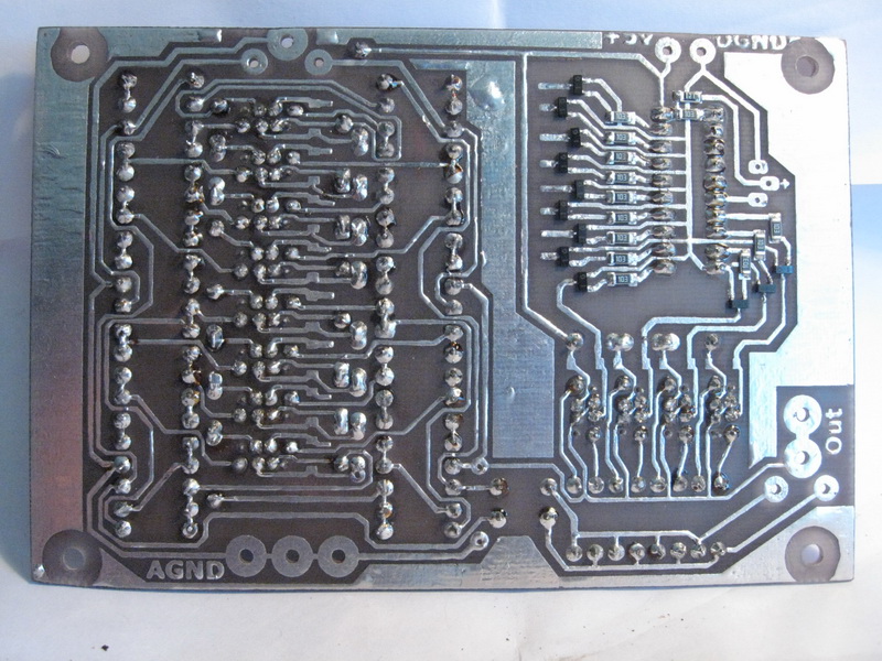
Another version. Bottom. Sealed
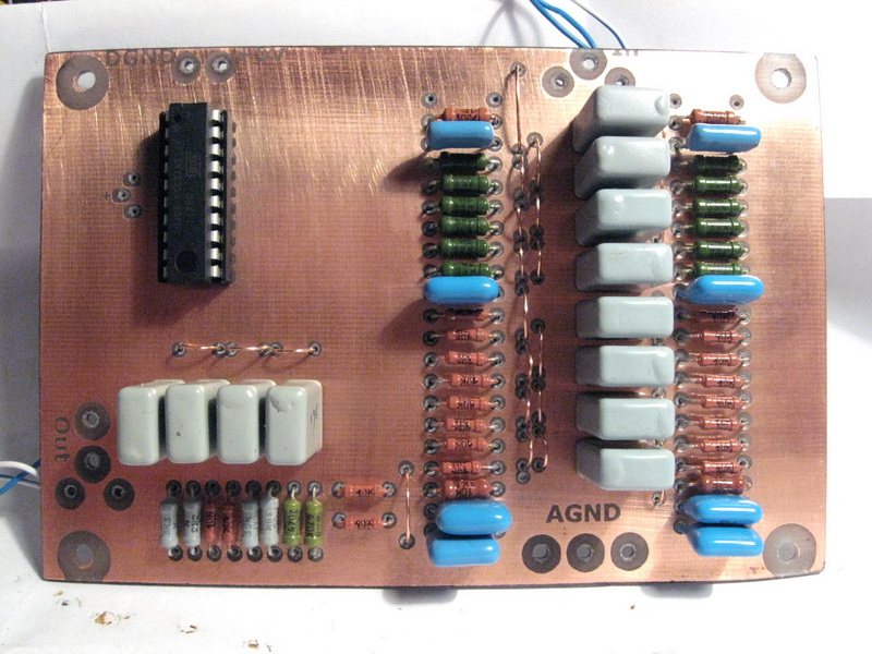
Another version. Top
Sukhov from the "Radio" magazine
Lynx preamp
I did not accidentally put the last two schemes side by side. I started with Sukhov. Purely from the tone block. Matched the resistance with the volume control. Oper was OPA134. So what? It didn't sound like much. As for bass, it's still nothing, not bad, but no treble at all. I, like everyone else, probably do not listen to music with an oscilloscope, but listen with my ears. The sound is extremely disappointing. I fiddled with this circuit a little more, and soldered Lynx. And why solder there - I changed the denominations and it's ready, I left the operas the same, OPA134. In Lynx'e there is no such sand on treble, the sound is more decent, but still treble is not beautiful. And I would not like to hear this in the performance of radio components.
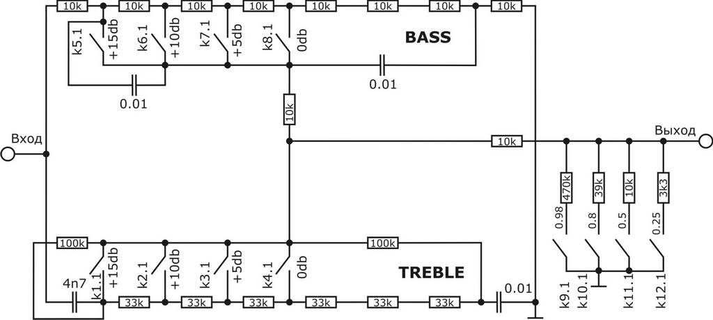
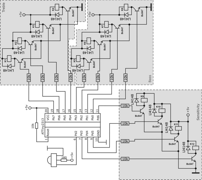
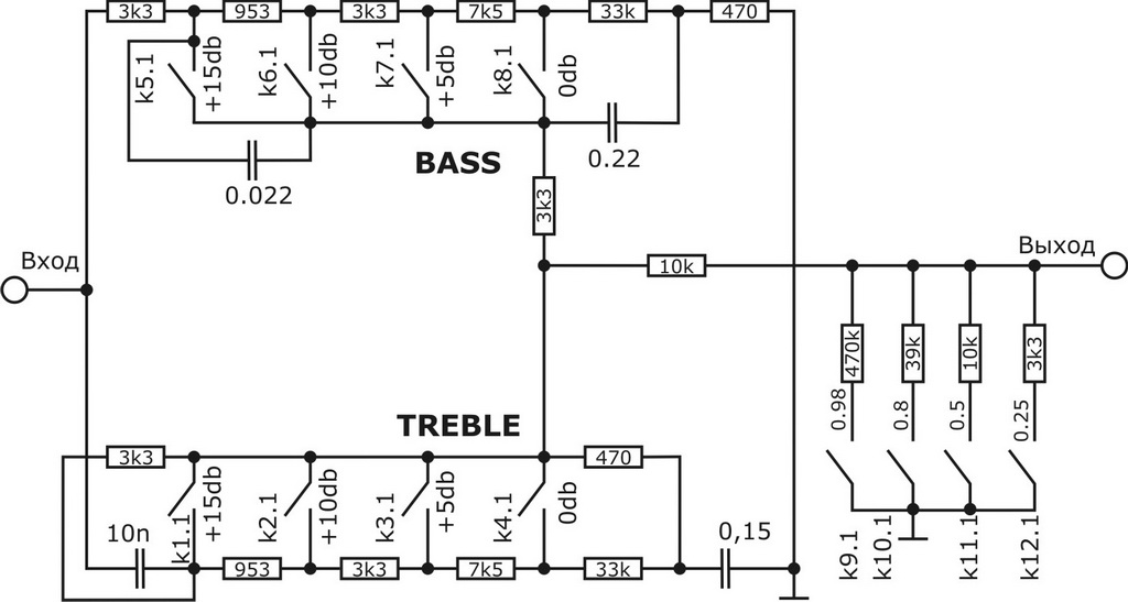
Matyushkin
Matyushkin pcb
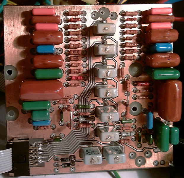
Matyushkin pcb is done
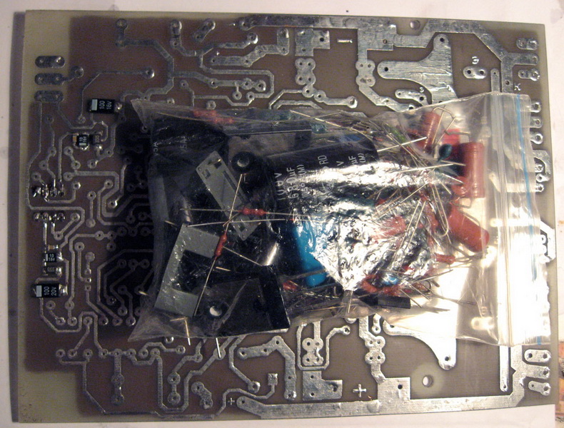
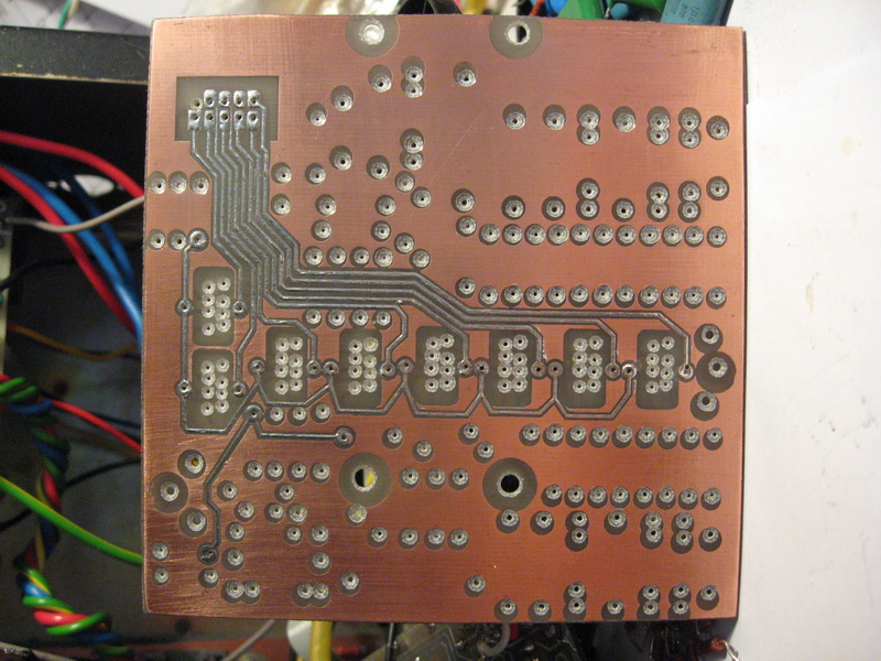
Matyushkin pcb bottom
Matyushkin pcb
Matyushkin pcb
Matyushkin pcb
Matyushkin pcb
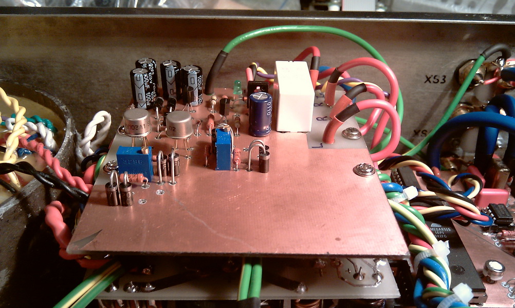
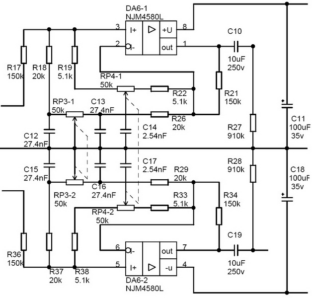
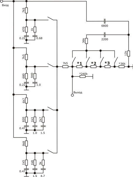
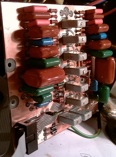
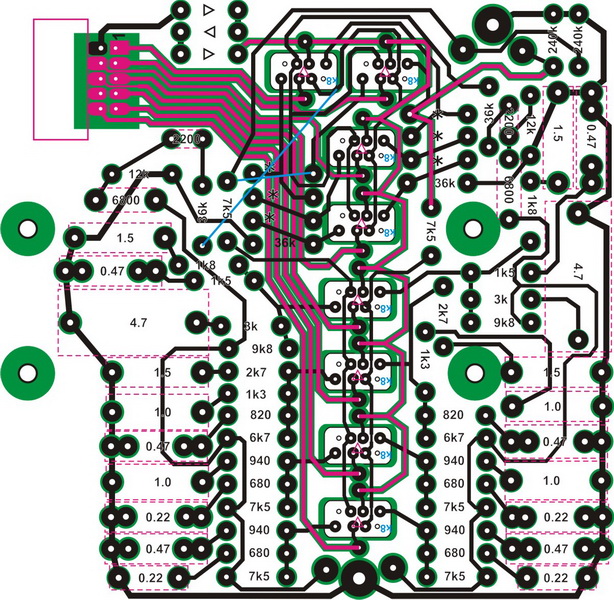
And then I caught my eye a thread on this forum, from which I learned about Matyushkin's tone block. I decided to solder it, because there was nothing else left, well, almost nothing. Assembled on a breadboard. Connected. And I realized that there is something in this sound. I made a seal, soldered it, connected it and realized - this is exactly the sound that I was looking for. Bass - no words, just gorgeous. Trible - in general, a charm. Stopped at this option. I slightly changed the scheme to suit my ears, so to speak. After, I redid the signet, and this is the final version. Resistors marked with an asterisk (*) should be selected by ear, strictly for your own ears. A 240k resistor with an asterisk can be set, or you can not set it, you determine experimentally, or you can not 240k, you can 100k, or 470k, or 47k.
Generally speaking, a passive tone block ala Baskandal is a milestone in the history of audio technology. With the use of such timbral blocks, an unthinkable amount of equipment was made, both in the east and west, and in the USSR (in foreign countries, of course, much more than in the USSR). Another common option is the inclusion of a passive pre in the op-amp OS. And everyone was happy with everything, both the sound and the quality. But as time went on, the possibilities changed a lot and now there are even more options for preamplifiers. A good question is why there are so many schemes of preamp and they are very different and what to choose for yourself? The answer is simple to the point of banality - everyone has different ears, in order to choose something for themselves - you need to solder it and listen, and not 5 minutes or 10, but much longer and of different genres of the topic. And finally understand - yours or not.
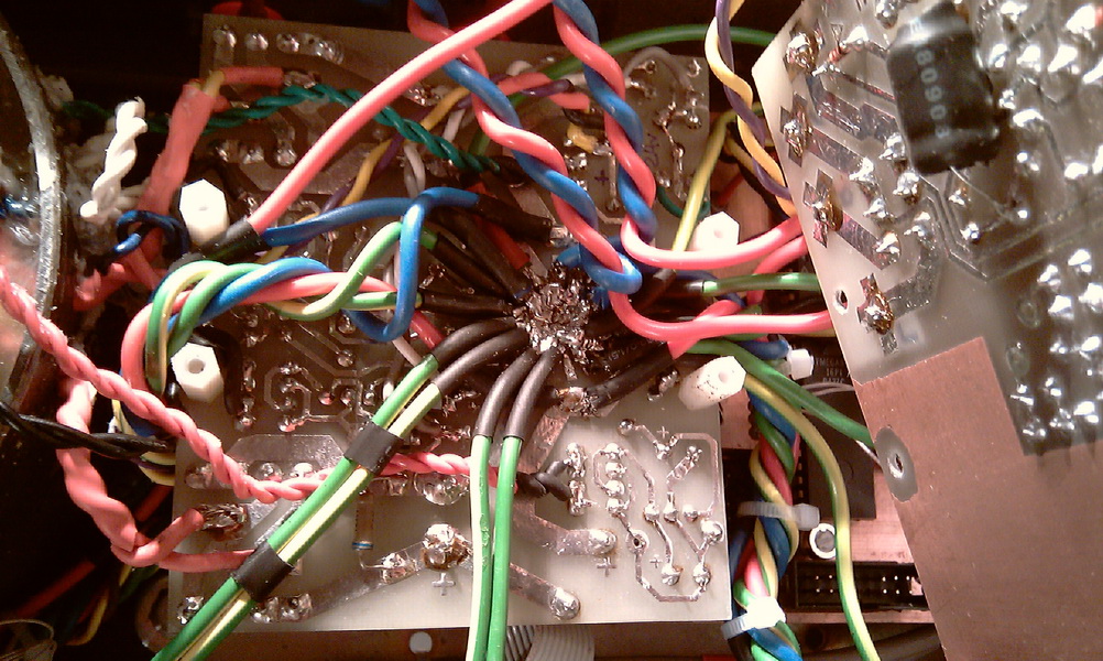
Well, it seems that all the nodes are soldered, almost individually checked - everything works, there is no noise anywhere, no buzzing, no interference. We connect our devices into a path and this is where clowning begins with the matching of input and output resistances. The first connection option: input relays, buffer on AD810, PGA2310, tone block, WP - there is no interference in this connection, nothing is heard from the speakers at all, even when you firmly stick your ear into the speaker cone, you can barely hear the thermal noise of radio elements. But this is the worst option. I explain. Sensitivity UM 1V. Before Matyushkina weakens the signal by 15 times. In total, in order to have 1V at the output of the timbre block, you must have 15V at its input. The PGA2310 simply cannot do this, it has an absolute maximum of the full voltage swing at the output of 27V, i.e. the maximum amplitude is 13.5V and at the same time we will not get the nominal input voltage at the WP input. In addition, these are the maximum allowable values. I will not rape the PGA with this method. You can stick another buffer after the PGA, which will pick up the signal, but at the same time, the thermal noise becomes audible more clearly and we come to the next option. We change the order of connecting devices in the path: selector to relay, PGA2310, buffer to AD810, tone block, WP. At the same time, at a distance of 20-30 cm from the speaker, thermal noise becomes audible. But we remember that the PGA scale can be +31.5 dB. The level of thermal noise does not change with increasing signal level, which is good. I made the buffer Ku of the AD810 equal to 2 - and that could have been less. In general, there is still something to work on. There is no general scheme, because soldered and coordinated cascades on the fly, without fixing almost anything on paper. Well, there’s nothing wrong here, on the Internet there are buffer diagrams and PGA2310 / 11 connection diagrams, you can choose some for yourself.
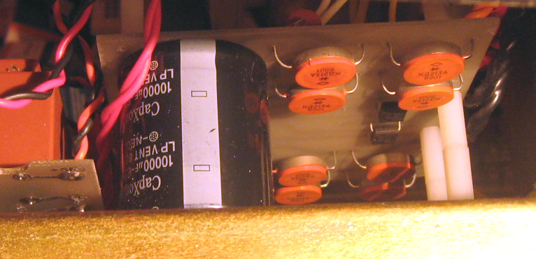
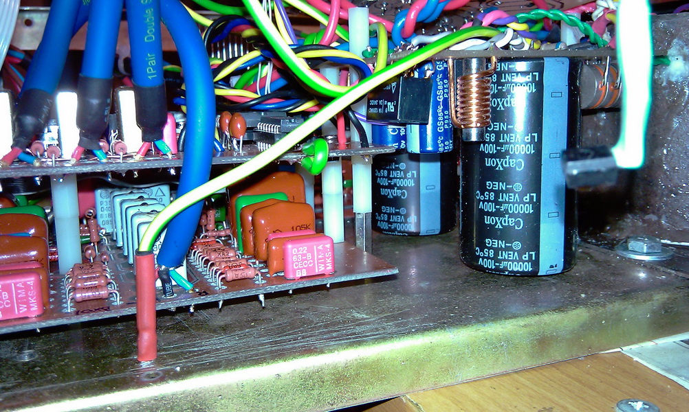
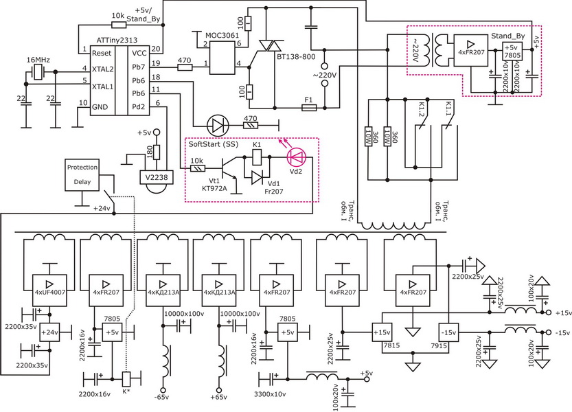
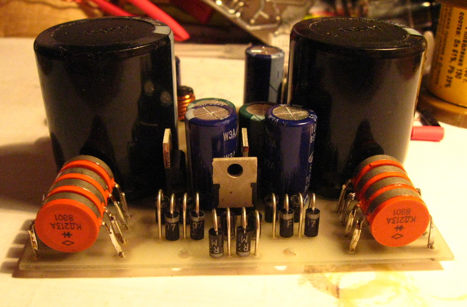
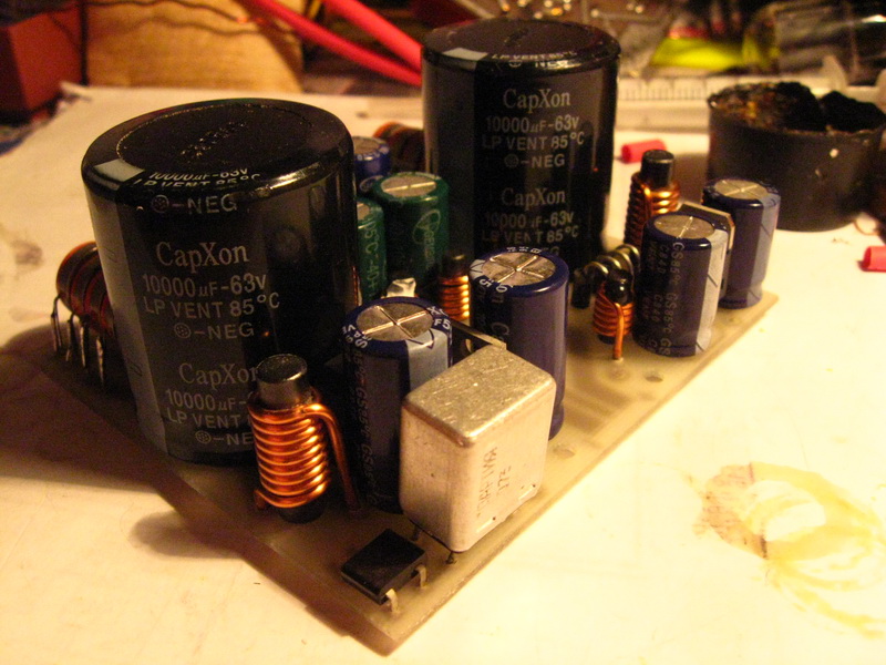
Power supply
Everything is very classical - bridges, caps, coils in some places, in general, standard. In the final version of the feeder, the 63V capacities were replaced with the same ones, but with 100V, due to the fact that after rewinding the thor, I raised the supply voltage to +/-65V. Immediately after rewinding, the thor was welded in paraffin right in the sarcophagus and right on the gas stove. After that, the sarcophagus with the torus was filled with epoxy resin.
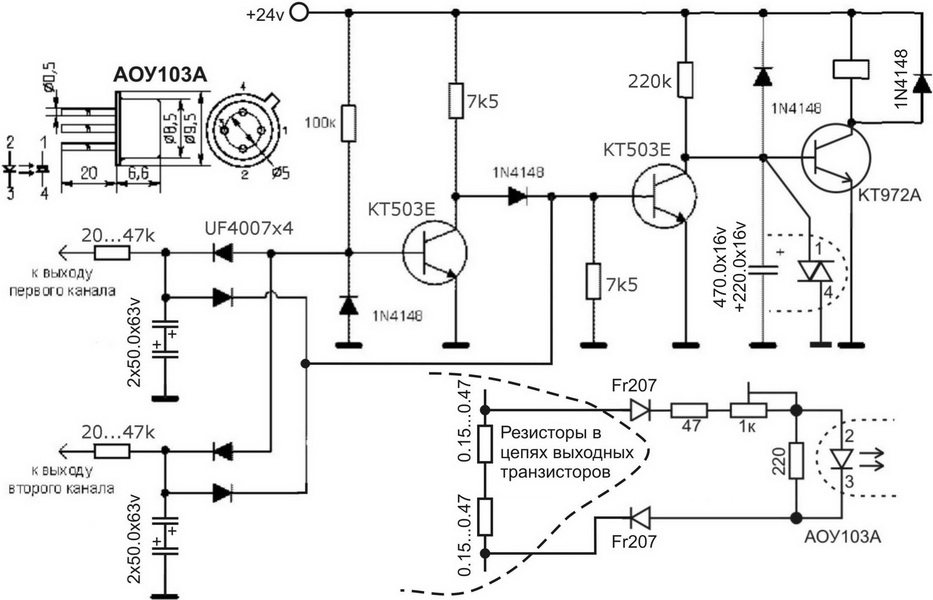
Everything is simple and in the protection unit. Applied Kotov's defense. I pumped it lightly (the author is aware). I added an optocoupler and a couple more details for current protection. If you remember, I did not solder it in the WP amplifier. Yes, in fact, I haven’t connected this one yet, although it was successfully tested. It solves one problem - when the current is overloaded, the acoustics are turned off. And what about the amplifier? Yes, God be with him. In any case (except for the S30 and cheaper), the cost of the speaker, even the same S90, is higher or comparable to the cost of parts per WP channel, not to mention imported acoustics. And even more so, not to mention repairing the speaker and repairing the amplifier: where there is more crap - when replacing a speaker, for example, a woofer, or when replacing a transistor, even a dozen transistors, including weekends.
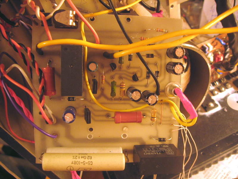
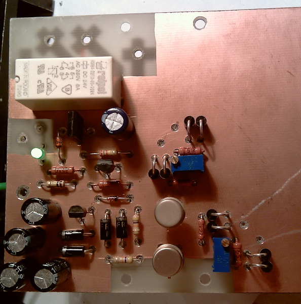
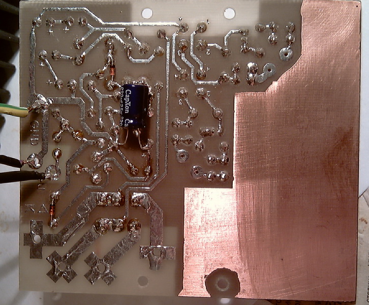
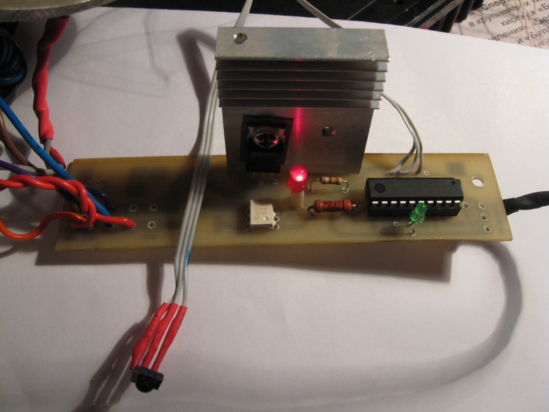
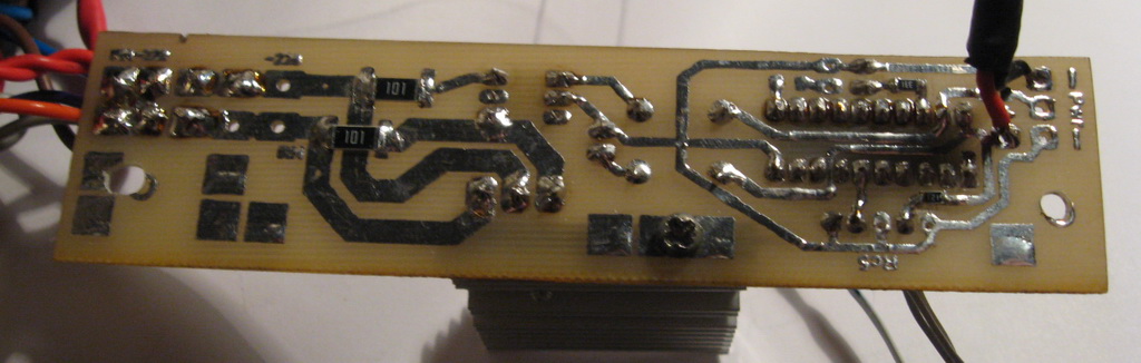
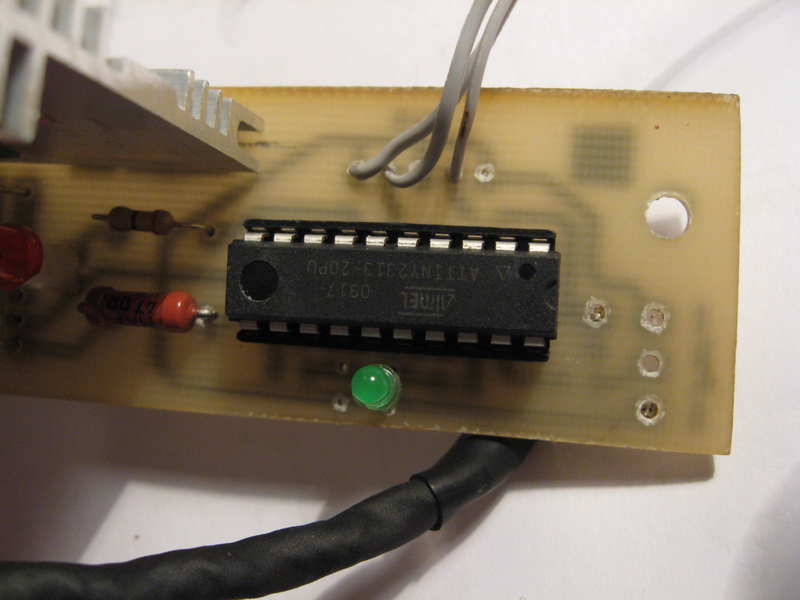
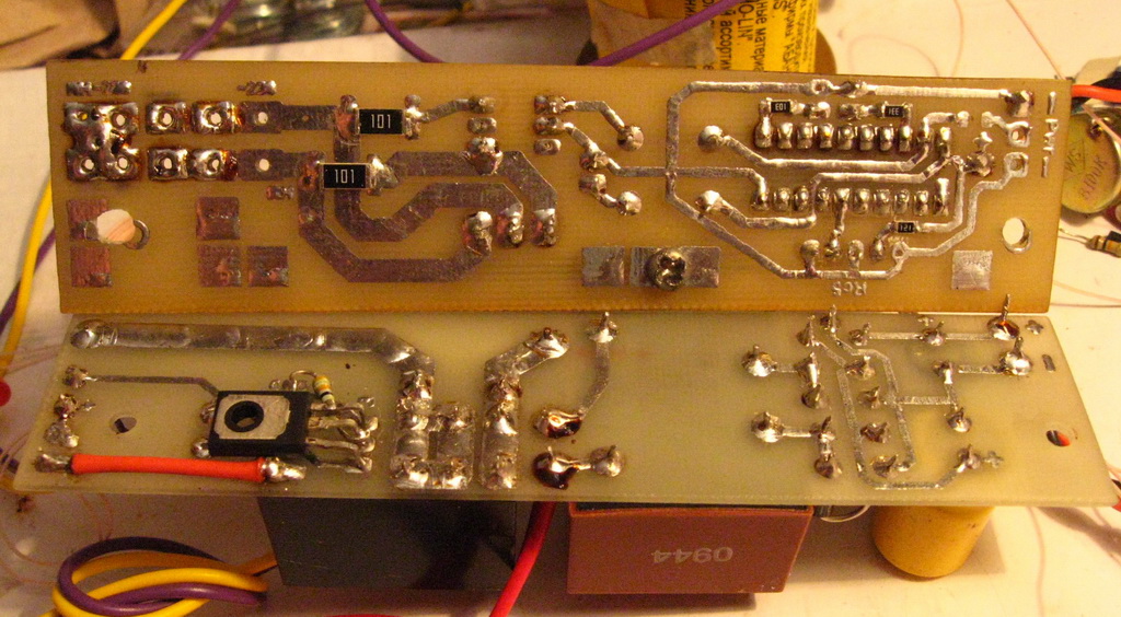
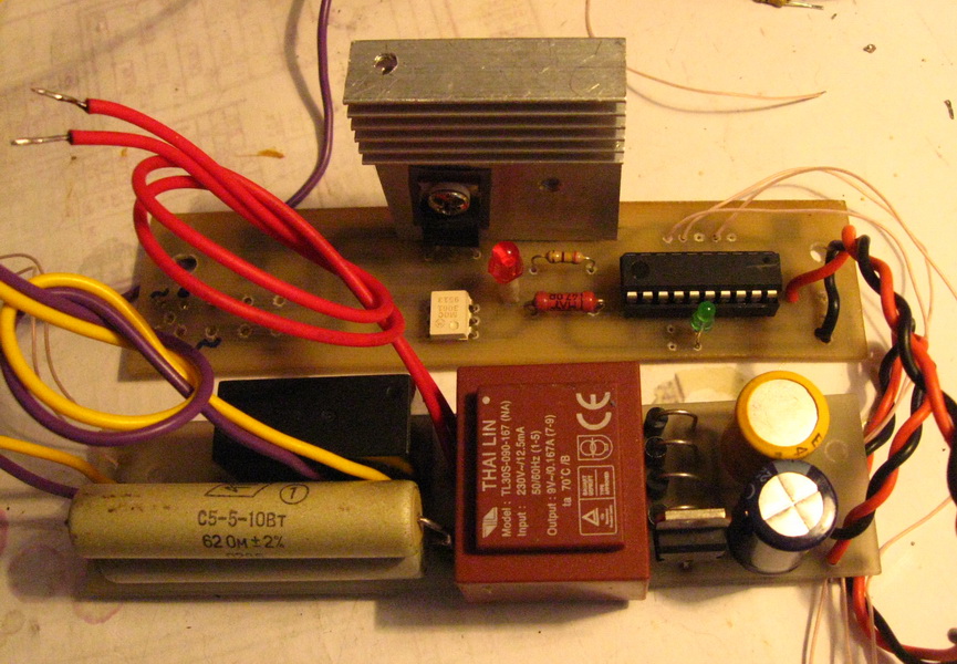
This is the standby power supply and soft start scarf. The diode parallel to the relay coil was replaced by FR207, the relay was also replaced, a capacitance of 4 microfarads X 630V was installed in parallel with the relay contacts. The relay is controlled by atTiny2313. Activates after 4 sec. after power supply. I spied a couple of lines of code from Danzup, the rest of the code I threw myself. The firmware is here. Responds only to the on / off button RC5 remote control. Look at the photo.
Side devices
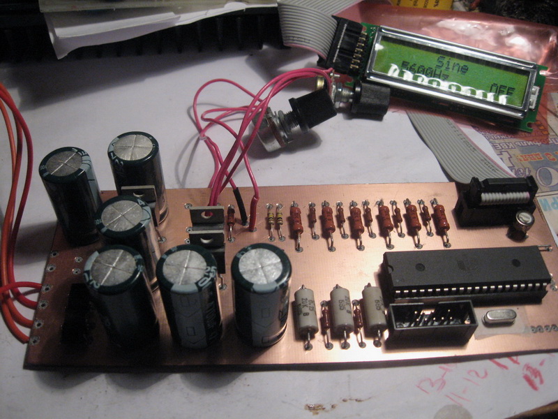
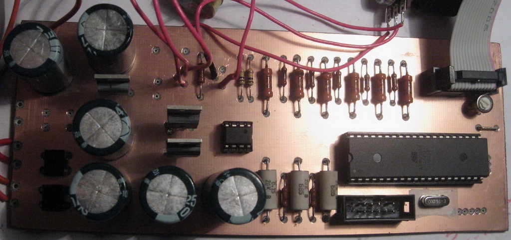
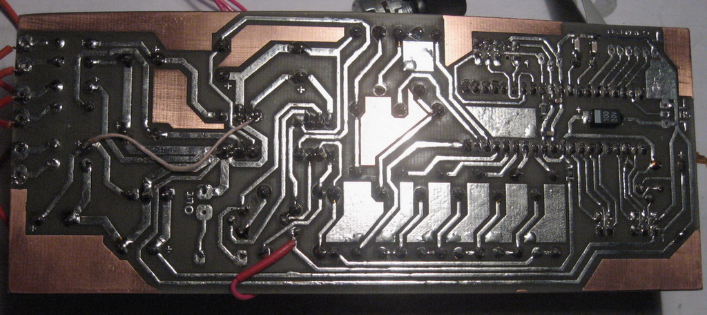
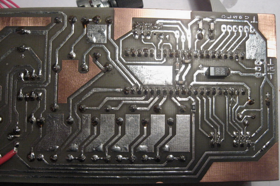
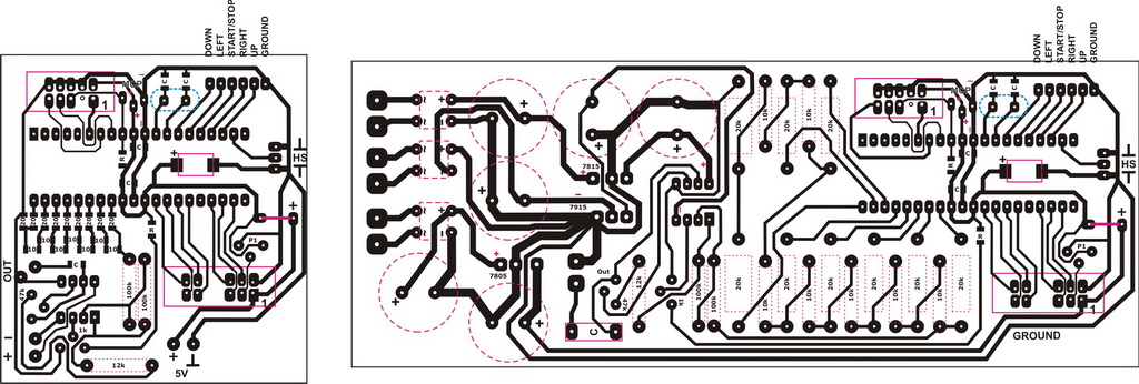
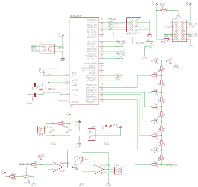
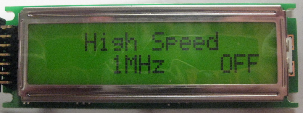
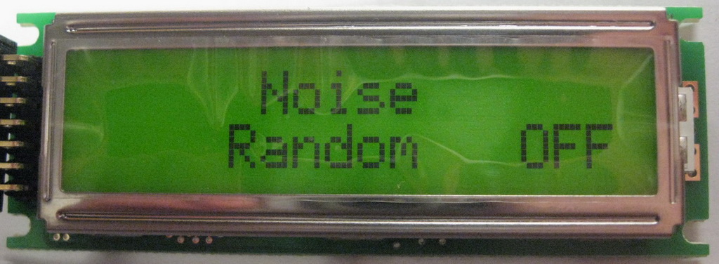
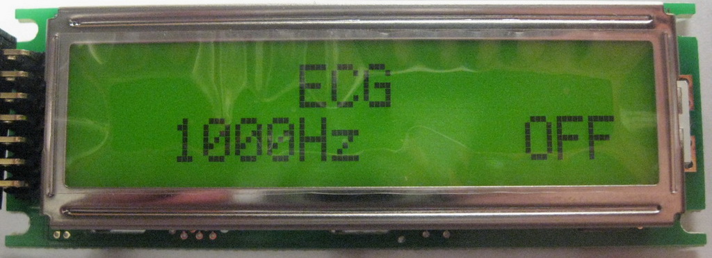
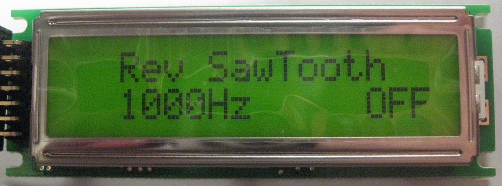
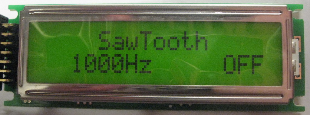
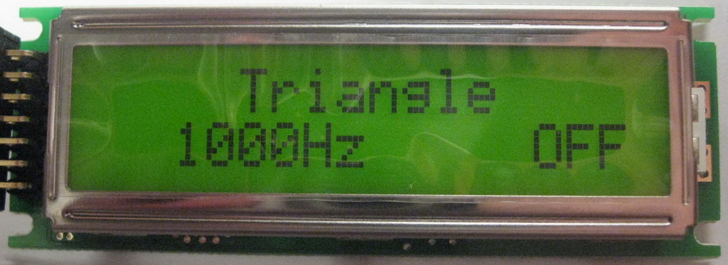
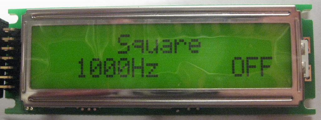
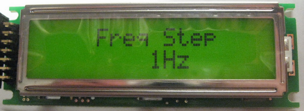
Sound Generator. The generator that I took from work to test WP has a slew rate of 24V / µs at the output. This is not enough in my opinion. Found online ATmega16 LF generator . Just slept. Turned on - everything works. The firmware is on the page on the link, the discussion on the link too. Here I will give only a photo and a board of my version. His only fee here. Resistors should be accurate. I put one of the denominations at 1%, the second denomination - 0.1%. Not SMD, but decent enough.
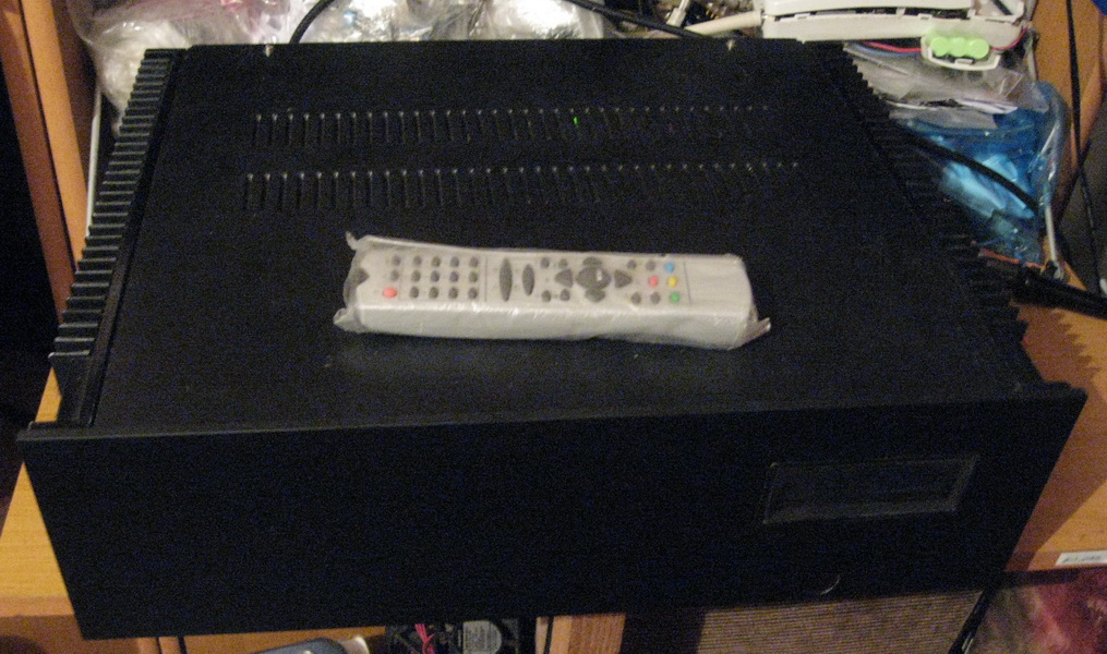
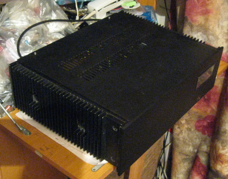
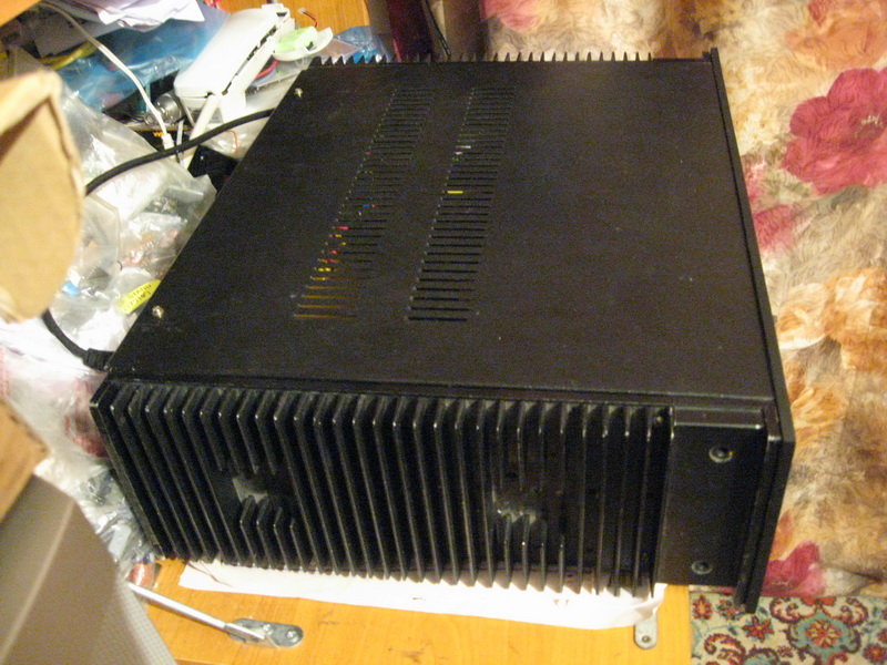
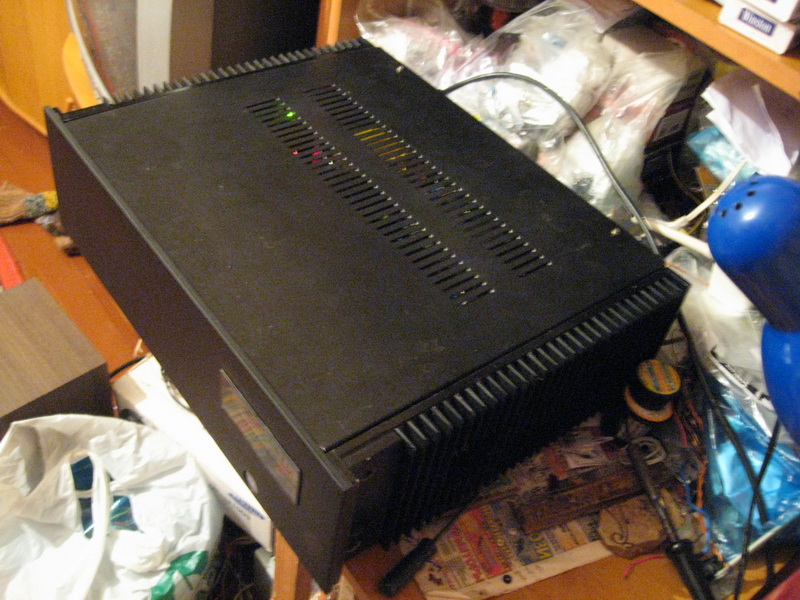
Case and front panel
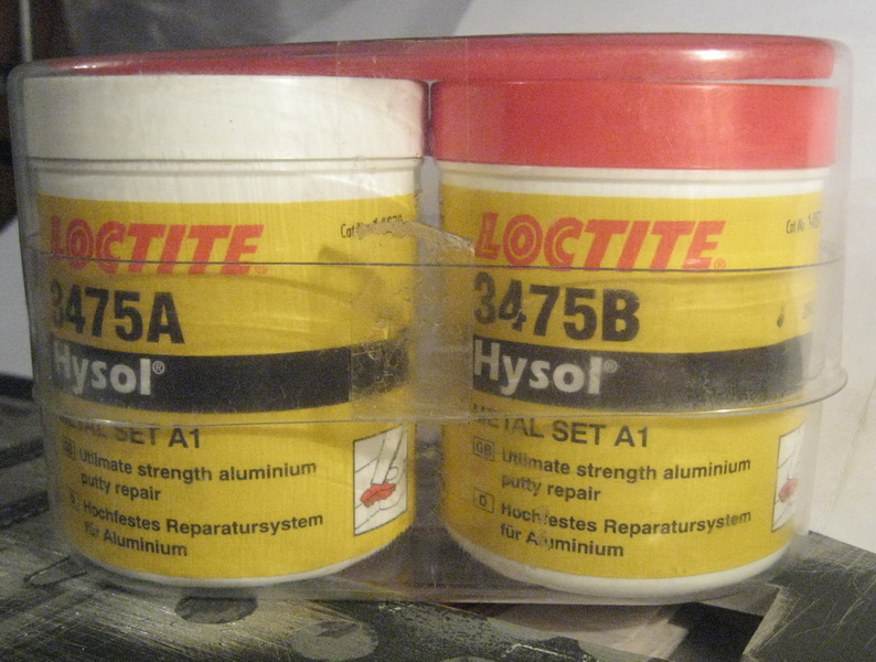
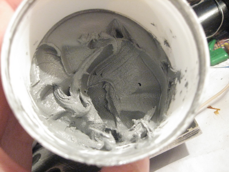
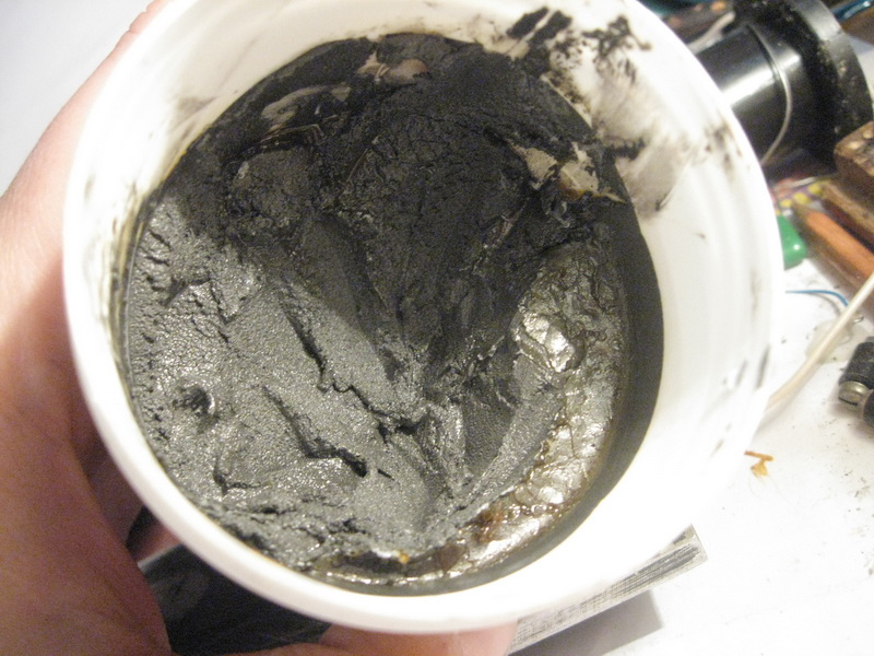
As I have already said, I got the case along with the almost ready-made Junior Power amp in the form of a kit. The front panel has undergone a number of changes, unlike the rest of the case. The front panel was removed and sanded down to metal. Next, I took just such a thing in the form of two jars - in one - resin, in the other - a hardener, as well as a spatula for mixing and applying. There are two types - for metal and aluminum. As you can see, a similar mixture can be made independently by simply adding aluminum or metal filings to the epoxy resin. The grooves, holes and slots for applying the mixture on the inside of the panel were sealed with getinax strips to prevent the applied mixture from creeping out through the panel. Further, the places of application are degreased, the mixture is thoroughly mixed and applied. The final hardening time is 24 hours, but after 12 hours it is already possible to gently work, for example, to drill holes. Sanding, I think, is too early, I waited until it hardened completely. Next, skin with a diamond mesh. Yes, the thing is very hard for manual processing - I did everything the old fashioned way - I wrap a wooden block with sandpaper and slowly, party. The bar was relatively short in length, about 25 cm, to ensure uniform removal of excess material over the maximum possible area of the front panel, in general - to get it without holes and bumps.
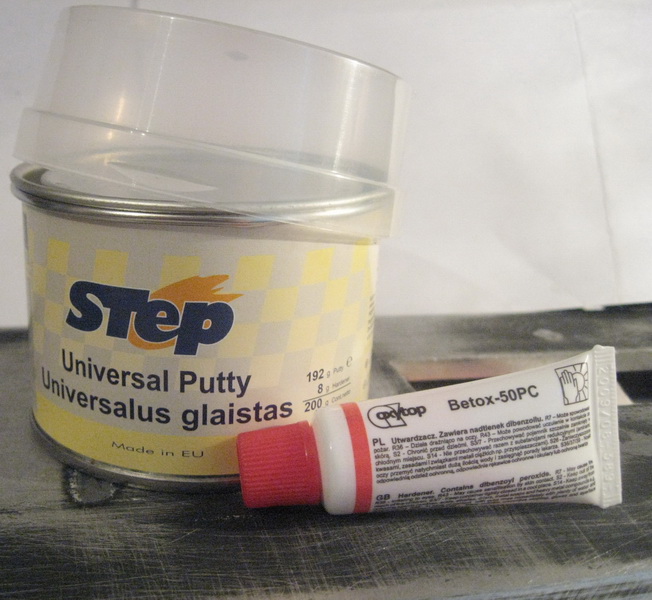
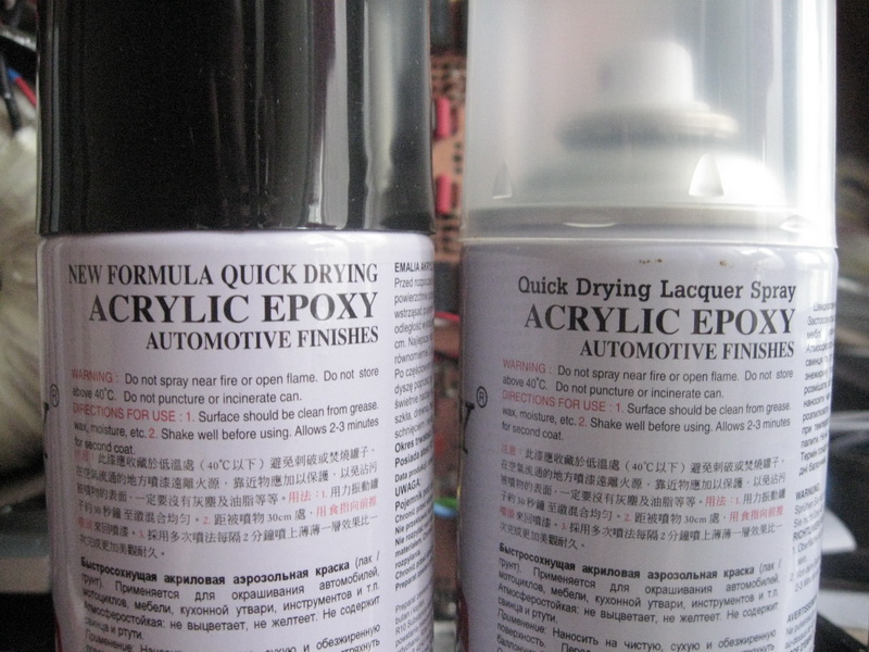
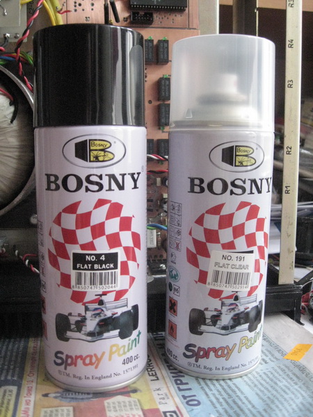
After complete hardening and removal of all excess, we apply putty - an ordinary automotive putty for metal. But it dries quickly. After, we wait until it dries and again skin the panel, remove the excess putty. We use sandpaper of varying degrees of graininess - as we grind, we go down from coarse to fine, we wash out all the small scratches and irregularities with sandpaper, slowly and carefully. We remember that we do not for sale, but for conscience. Here, I think, everything is clear. Paint (with a black cap) and varnish (with a translucent cap). I took everything matte - both paint and varnish, I really don’t like gloss. How to paint I will not tell - everyone knows. At the final stage, I cut out a circle from red plexiglass and inserted it into the front panel. Behind this glass is attached 2 IR receivers - one for on / off, the other - for the volume control. And I glued a rectangular glass on the window in which the LCD is installed. A photo of the case is below on the page.
Instead of an epilogue
Before both Holton channels were dismantled, one of the channels was tortured-lite. At the input - 8V amplitude, meander and I shoot the frequency response. At the end of the procedure, it was impossible to touch the radiator, it was too hot. But alive. After, I let it cool down for 15 minutes, I connected the speakers, there are no problems, it plays. I simply dismantled the boards, did not solder them.
WP sounds just fine. I really like. I don't even know if I've heard anything like it. It's hard to say... I'm planning to measure the rate of rise of WP. tinker with the small pre, with the buffer and the input and output resistances.
From the unreleased, there was an almost completed volume control of the L-attenuator type. Almost completed the firmware. Even tested something. In addition, the firmware contains the function of displaying the volume level on gas-discharge indicators of the IN type. Those. the first character is an ID with a "+/-" sign, then two IDs with numbers, and the last lamp with a "dB" icon. I even got all the lamps for this device. Well, he didn't make it to the end. Why? The answer turned out to be very simple - a simple analysis showed that I can’t stop, all the time I want to improve something, change, complete, replace some kind of cascade or something else. Therefore, I decided that it would be better to pump the volume control that is. And in general - it's time to tie up with the amplifier, otherwise it can result in an endless pumping of a very good device.
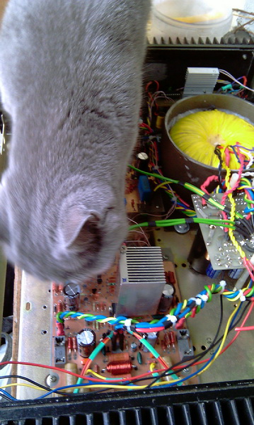
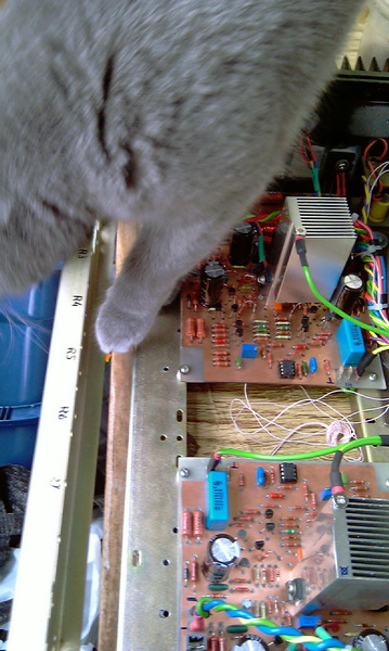
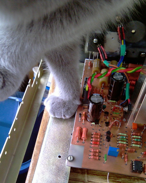
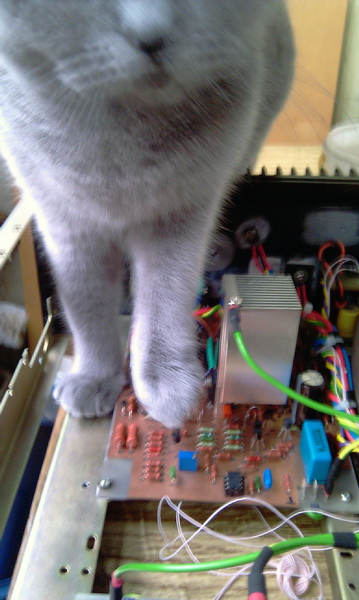
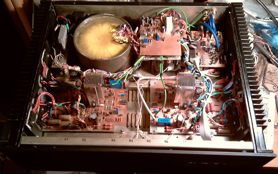
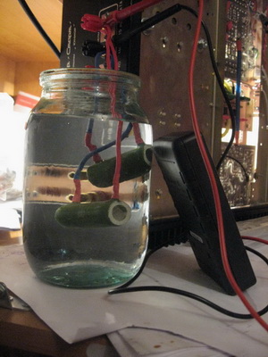
Before pouring the thor, the amplifier went through, as it used to be, quaklity checking. In the photo - my female cat Uma at work and several photos of the general plan.