My ZX-Spectrum (Leningrad-2) |
RU |
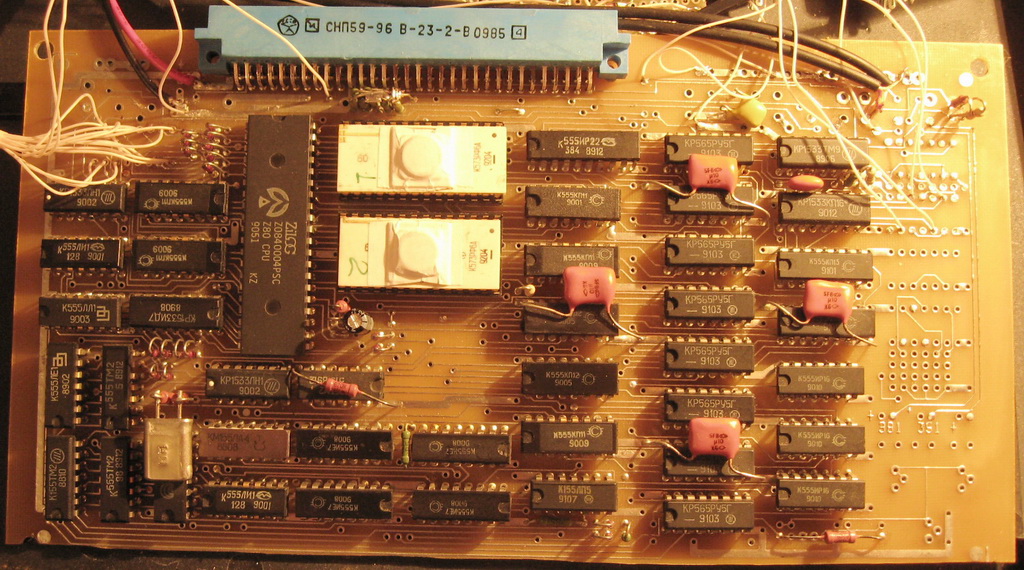
Restored one of my "childhood friends" - Leningrad-2. When I first turned it on, it was white. After soldering the RU5 line and the processor without ROM, a mattress appeared. I flashed the K573RF6 ROM with the classic BASIC "(c) 1982 Sinclair Research Ltd." Plugged in a keyboard. Works. There was an epic when connected to the TV. But everything ended well - I connected it to the TV according to the scheme from some Leningrad.
Programs are loaded from the tape recorder. Played great...
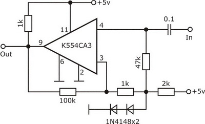
I had to tinker with connecting the tape recorder - most likely the input driver on the K561LN2 was covered. Therefore, a circuit was soldered for downloading programs from a tape recorder from the Baltik circuit
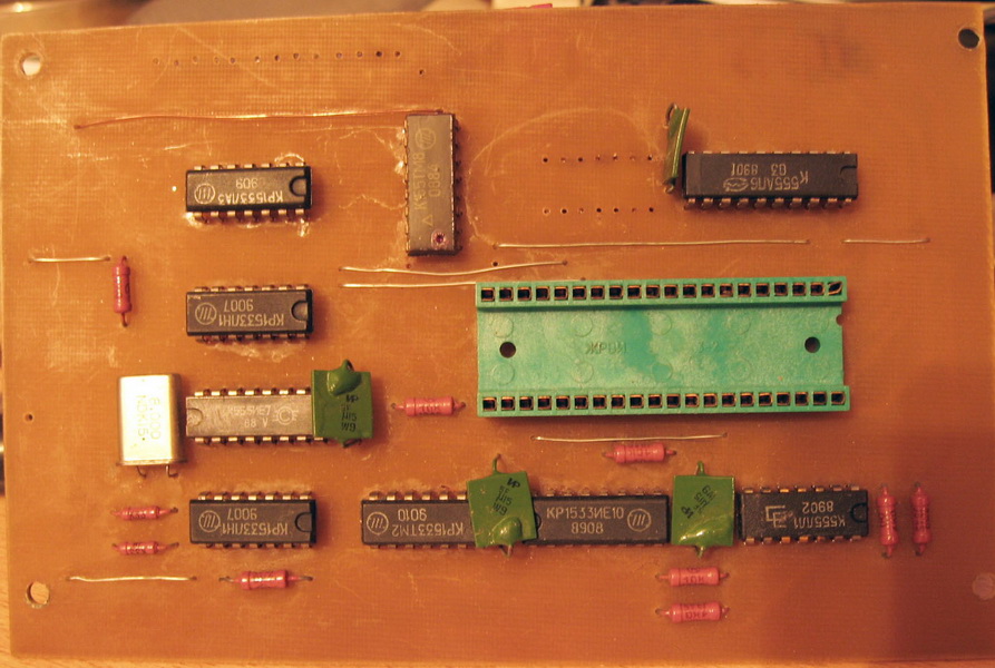
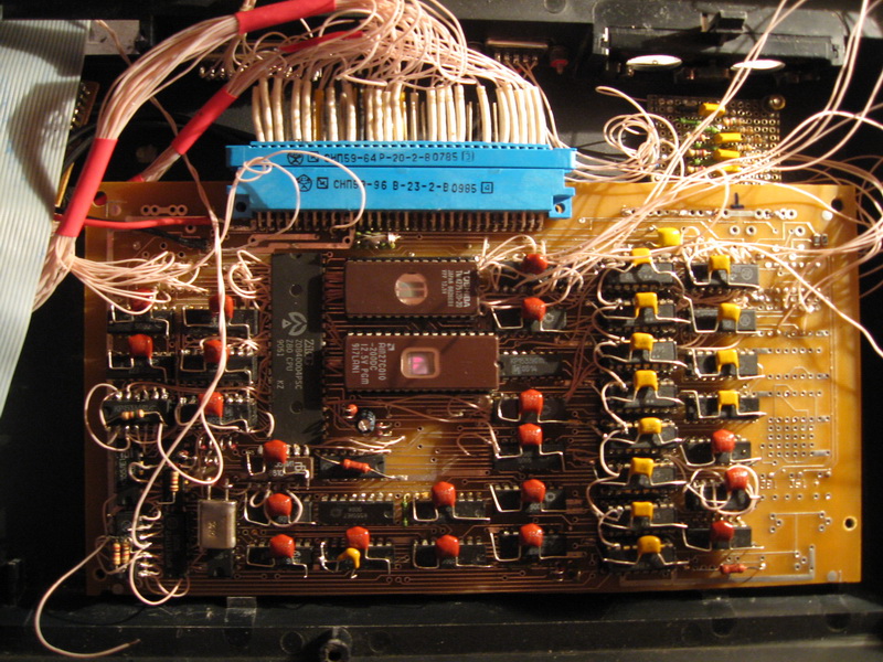
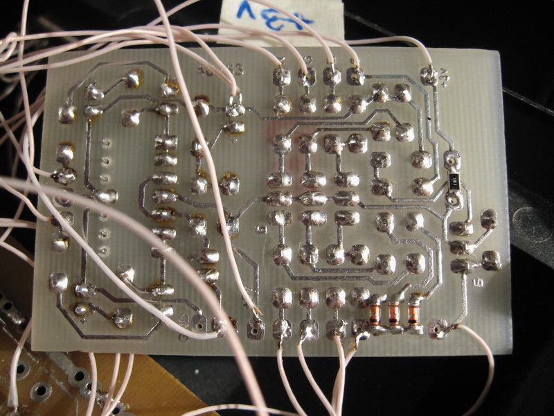
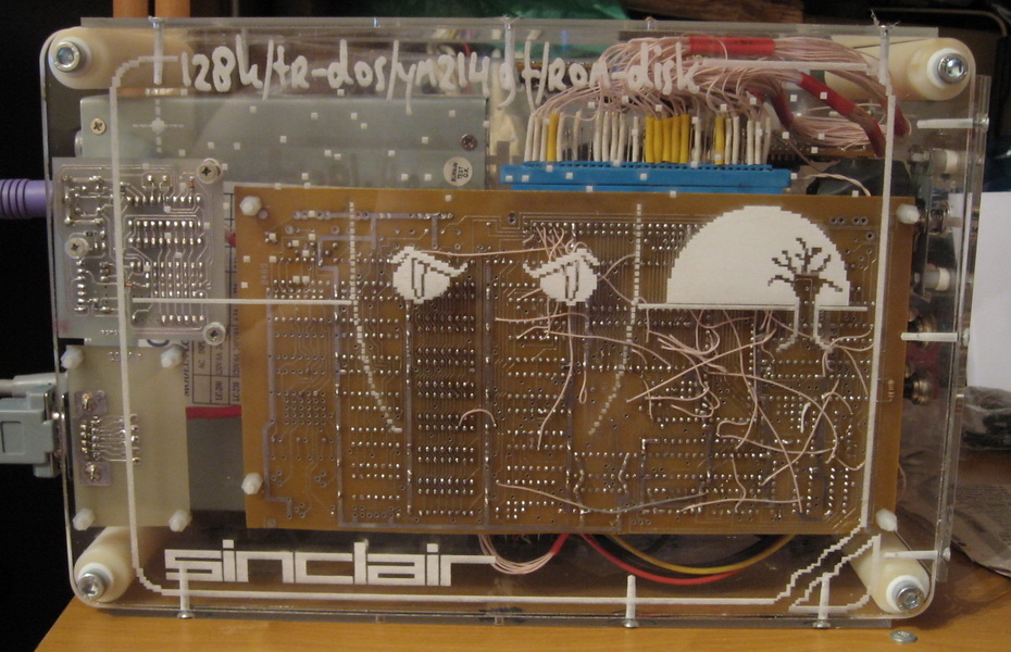
Leningrad-2/top
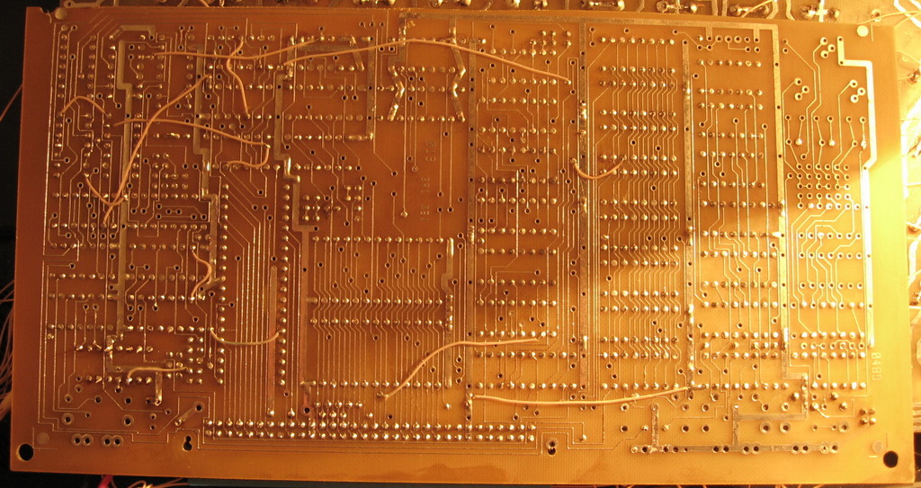
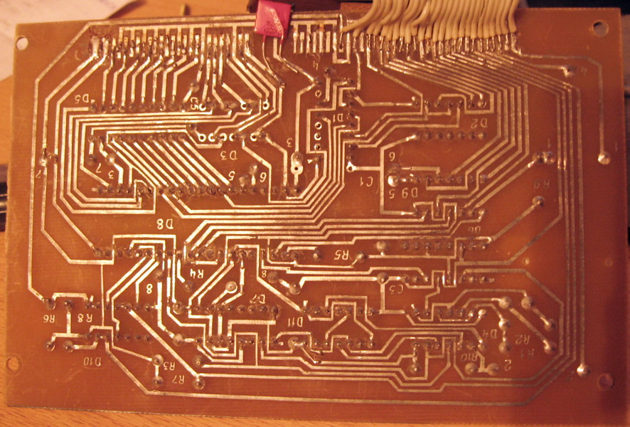
pcb/bottom
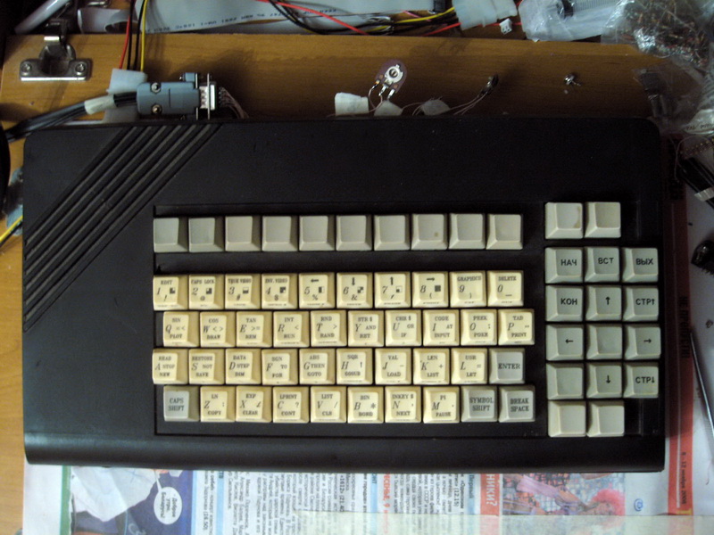
How it looked assembled with an extended / duplicated keyboard
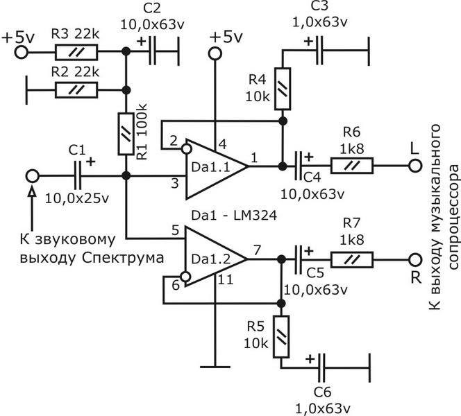
The scheme of loading programs from a tape recorder from the scheme of the Belarusian clone ZX-Spectrum - "Baltik"
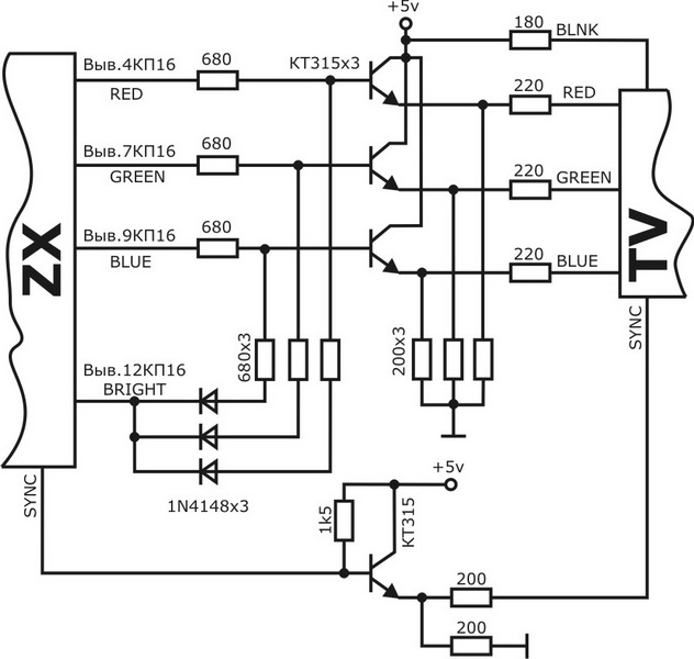
TV connection
CP/M и TR-DOS
This controller was connected to my Baltik a very long time ago. In Minsk, these controllers and ROM 27256 with a ROM-Disk, flashed under CP/M, were sold by the Sonnet cooperative. They were then behind Bangalore Square, on a certain street, the name of which I don’t even remember. I was with them then, I took the controller and ROM. This controller worked for me for quite a long time, until I switched to TR-DOS. There is no ROM firmware for this controller, the connection diagram was lost a long time ago, and TR-DOS is less exotic than CP/M. The little animal remained lying.
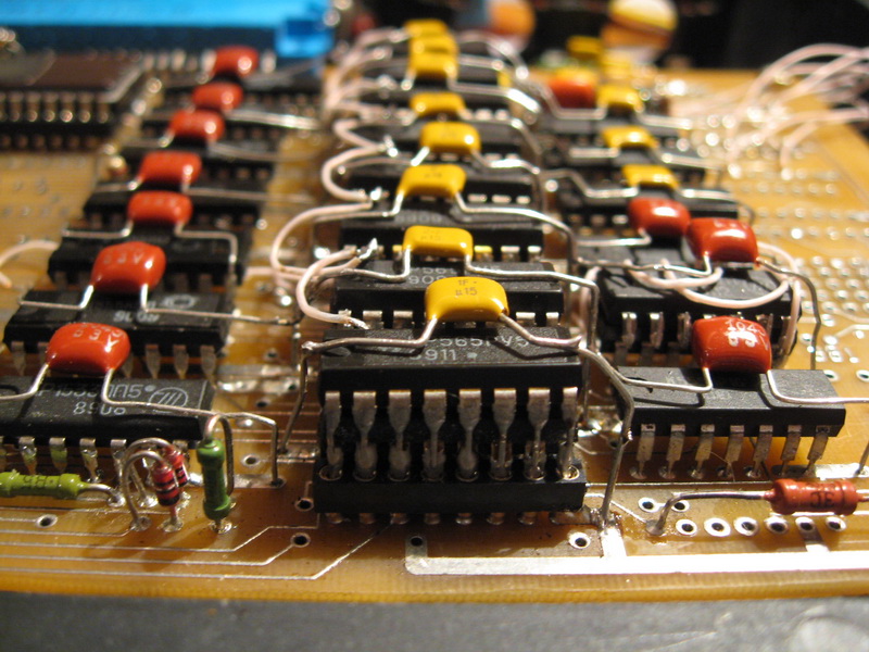
Connected С-48 - TR-DOS controller and expansion board С-1. I had a flashed ROM 27512 for a long time - I will use it. I also had to solder the circuit for locked entries in the "0" page. In the course of debugging, it was found that Leningrad-2 is very sensitive in memory chips - 565RU5, more precisely to the letter. As a child, I soldered RU5G, but then it was a standard Leningrad-2-48k. Then everything worked steadily, did not fail, did not fail. Having soldered another 565RU5G on the second floor, glitches popped up from everywhere. In addition, I had to buffer and at the same time somewhat delay the RAS signal - I installed two logical elements 1533LL1 one after the other. After digging around, I replaced all RU5G with RU5B - and lo and behold, almost everything was cured. It was only necessary to delay one signal with a capacity of 12 peaks - 12DD4 according to the Leningrad-2 scheme. Keep going...
CP/M. Top
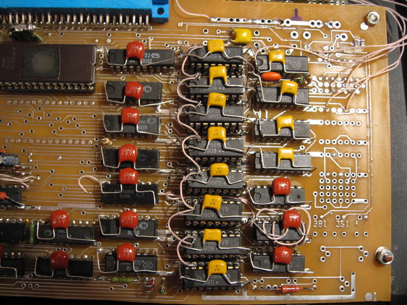
CP/M. Bottom
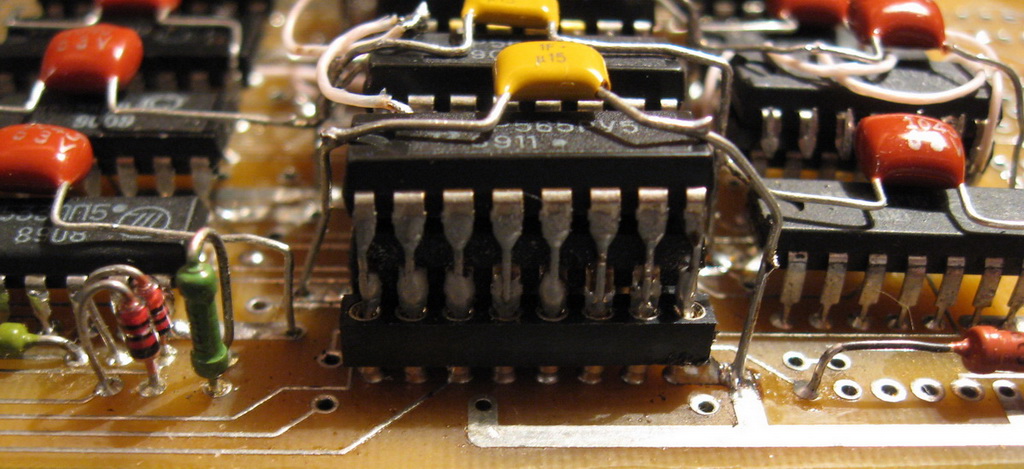
RU5 replacement
New RU5
New RU5
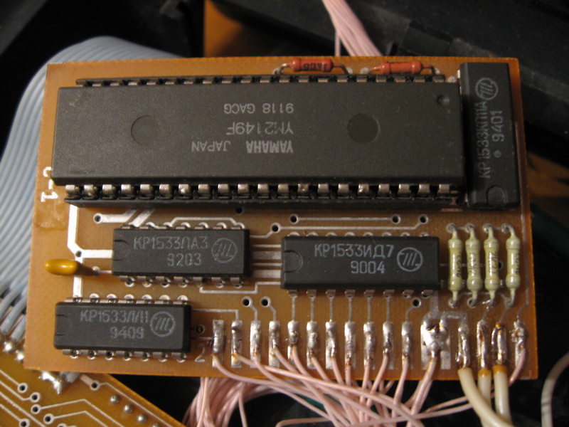
RAM 128к + AY/YM
TR-DOS С-48
TR-DOS С-48. Bottom
Leningrad-2
First I connected TEAC 5.25 to the TR-DOS controller, but the floppy disks that I wrote down when I was a kid were not read, well, something, of course, was read, but not all of them. After that, I connected a 3.5 drive, the benefit of online games for speck in bulk. By default, in almost 100% of cases, the 3.5 drive is set to "B". In order not to change the drive every time I enter TR-DOS, I soldered one wire on the drive board, and it became "A". After that, turbocharged 1818VG93, i.e. the drive heads are just 2 times faster to move when positioning.
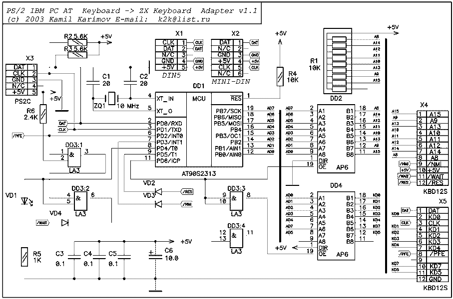
AT Keyboard Controller on ATTiny2313
This device allows you to connect a standard AT keyboard to the ZX-Spectrum. Schematic diagram taken from forum http://zx.pk.ru. I used ATTiny2313 with quartz at 20 MHz. Fuses set like this:
-------------------------------------
Name ! Default ! SET ! MODE
-------------------------------------
CKSEL0 ! on ! off !\
CKSEL1 ! off ! off ! > - q. external
CKSEL2 ! on ! off ! /
CKSEL3 ! on ! off !/
SUT0 ! on ! off !
SUT1 ! off ! off !
CKOUT ! off ! off !
CKDIV8 ! on ! off !
RSTDISBL ! off ! off !
BODLEVEL0 ! off ! on !\
BODLEVEL1 ! off ! on ! > - 4.3 V
BODLEVEL2 ! off ! off !/
WDTON ! off ! off !
SPIEN ! on ! on !
EESAVE ! off ! off !
DWEN ! off ! off !
SELFPRGEN ! off ! off !
---------------------------------------
However, I had to buffer the address bus connected to the controller. Buffer performed on K1533AP5.
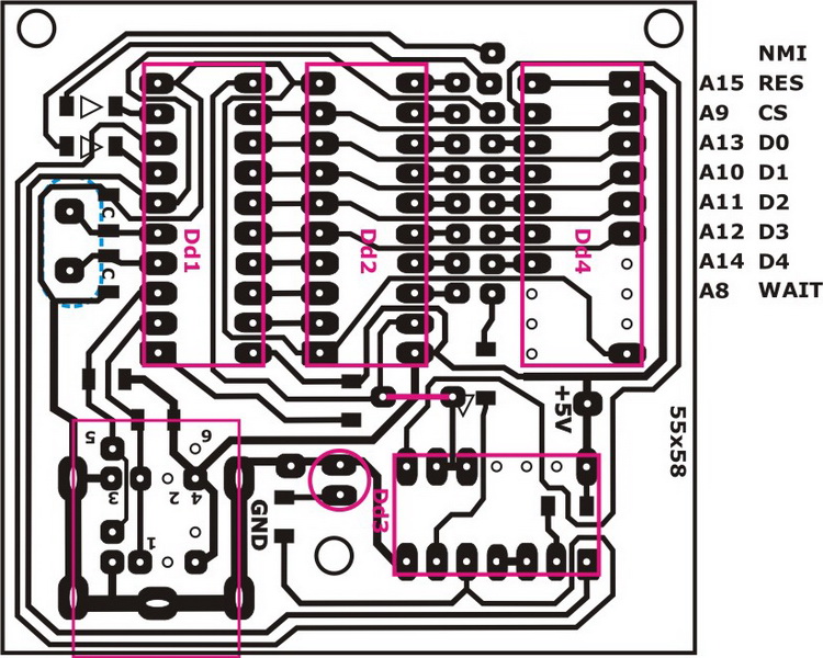
Keyboard controller diagram ZX-Spectrum
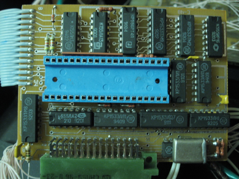
Controller PCB, wiring
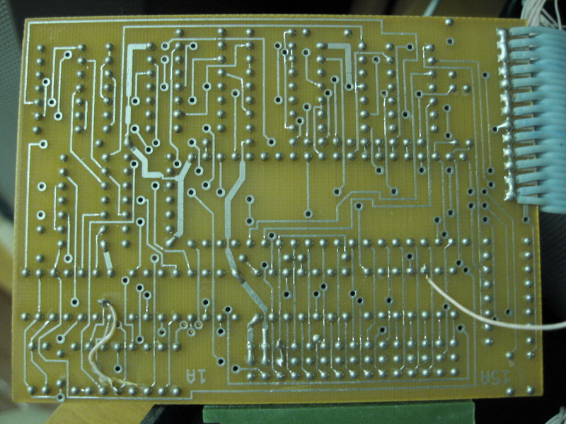
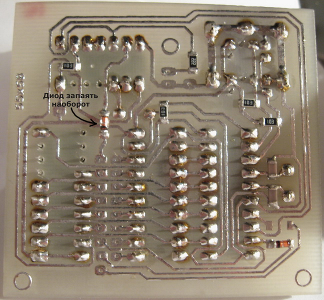
Controller circuit board, bottom view
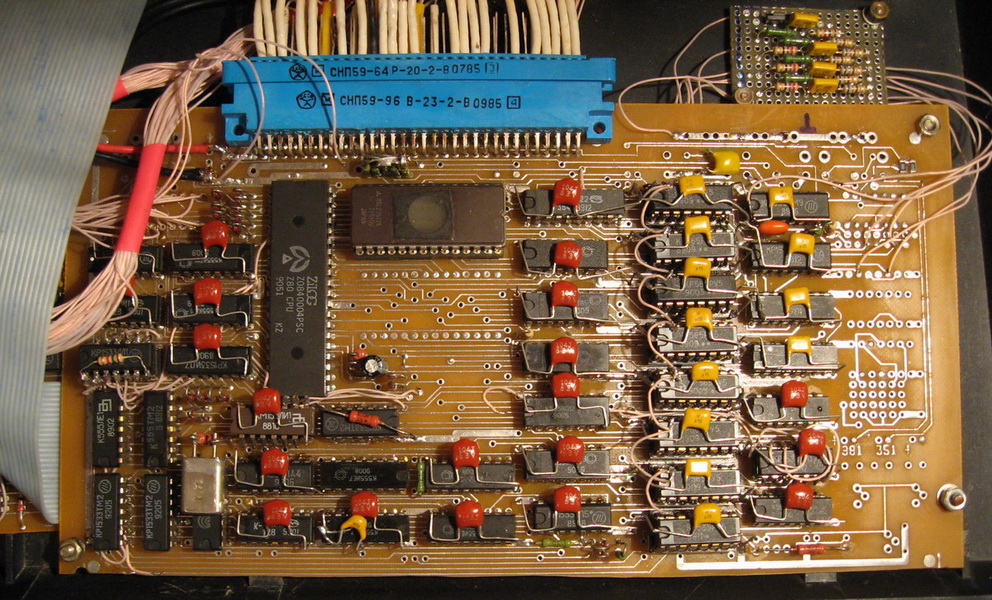
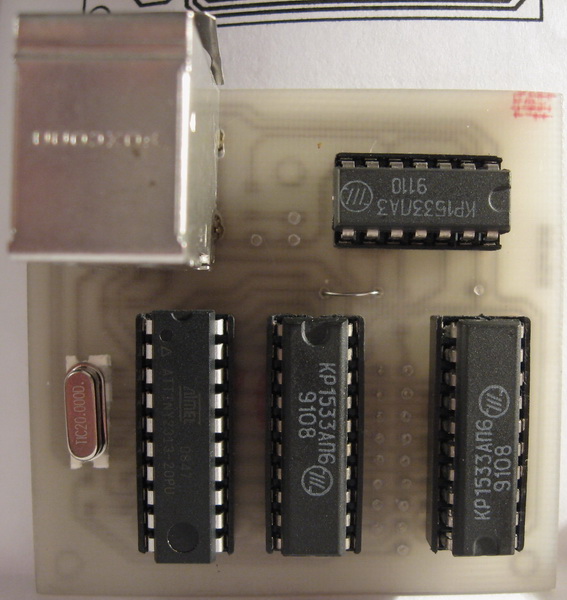
Controller circuit board, top view
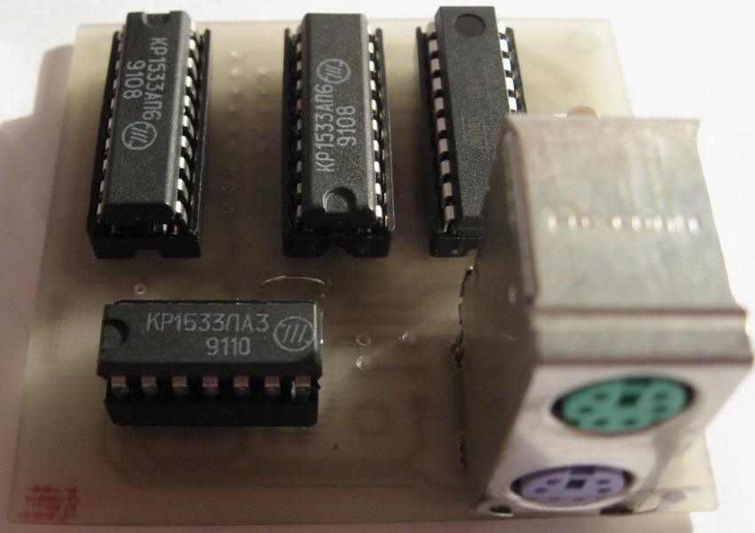
Controller PCB, side view
: : Firmware : :
ROM tuning
We remove BASIC and calculator from ROM 27512, and flash Quick Commander there and call it with one button. True, three more microcircuits were added 1533, but this is not a problem. When Quick Commander is invoked, it boots up and reads the floppy, if it's there.
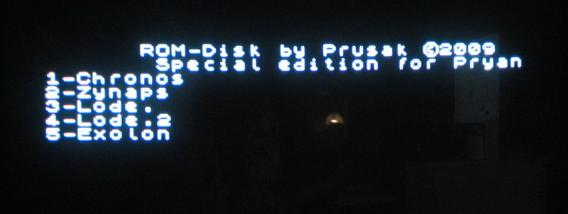
Schematic and firmware by Prusak. After the supply voltage is applied, we immediately enter TR-DOS, without a menu:
: : ROM 27512 : :
ROM-Disk
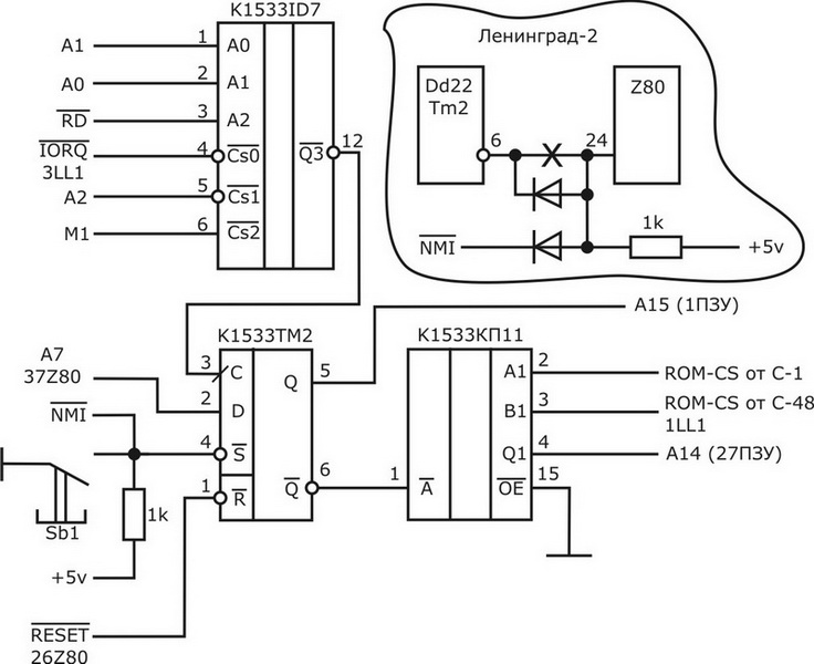
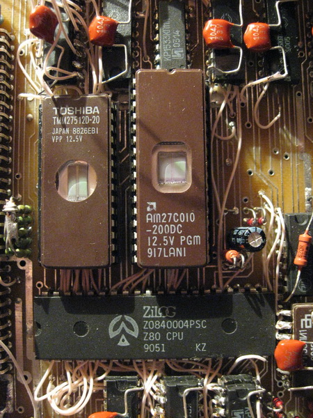
ROM-Disk uses ROM chip AM27С010 (32pin). Instead of the second panel, a 32pin panel is soldered under the original ROM, into which the ROM 27C010 ROM-Diska is inserted. The first two conclusions (1, 2) and the last two (31, 32) are bent to the sides, an MGTF wire is soldered to them. The board has a protective tape. Sewn up 5 toys. Calling the ROM-Diska menu - by pressing a separate button. Scheme and firmware by Prusak.
ROM-disk menu
2 candies
The ROM-Disk wiring diagram is below on the page... As well as some additional diagrams.
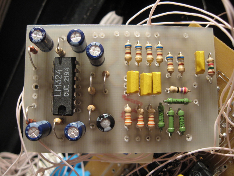
Video + Audio PCB
The TV connection diagram is located at the top of the page. The output resistors (27 ohms) are replaced by 300 ohms. I made a printed circuit board for this adapter. On the same scarf there is a beautiful mixing circuit for the BEEP signal (spectrum sound output) into both channels of the YM2149F.
Video
Audio
video and audio PCB
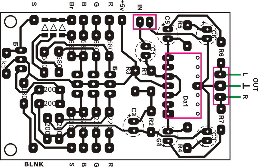
video and audio PCBв
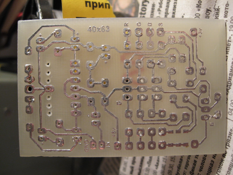
video and audio PCB
Controller PCB, side view
Tuning schemes Leningrad-2
Select ROM
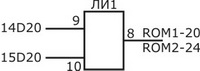
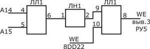
RAS buffer
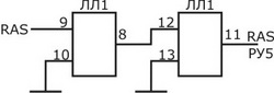
27С512 (ROM1) connection
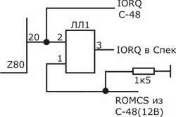
IORQ
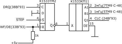
KR1818VG93 turbo mode
Prohibition of writing to the "0" page
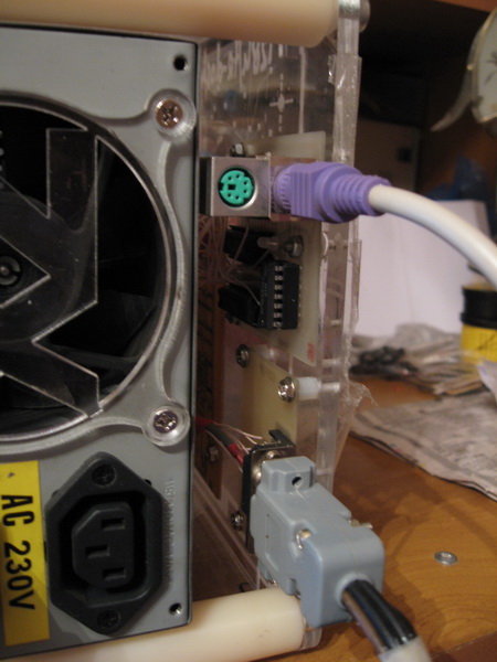
Buffer A8-A15. Used when connecting PS/2 keyboard controller
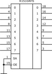
Diagram of ROM-Diska and shadow ROM. Part of the circuit used in "ROM Modding" (higher on the page)
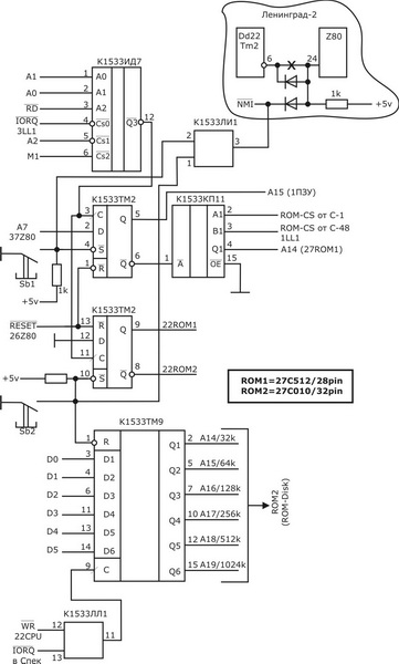
In addition, several connections must be made:
1. 12TM2, which is under the quartz in the TR-DOS controller, connect to a common wire.
2. 11 and 12LA2 connect together.
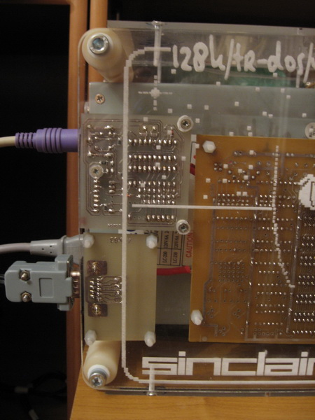
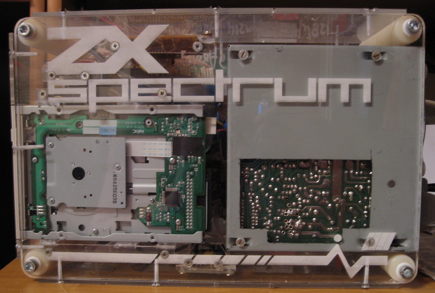
Case
I made the body of the Spectrum from Plexiglas. The side walls are 6mm thick, the rest are 3mm thick. Some surfaces are laser engraved on a CMA 1680 machine, on the same machine all these walls are cut out along with all the holes.
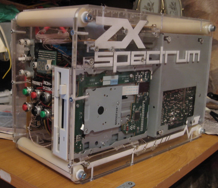
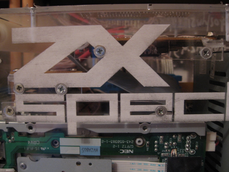
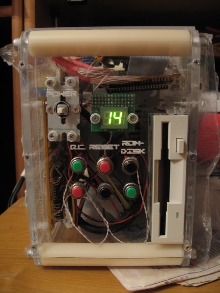
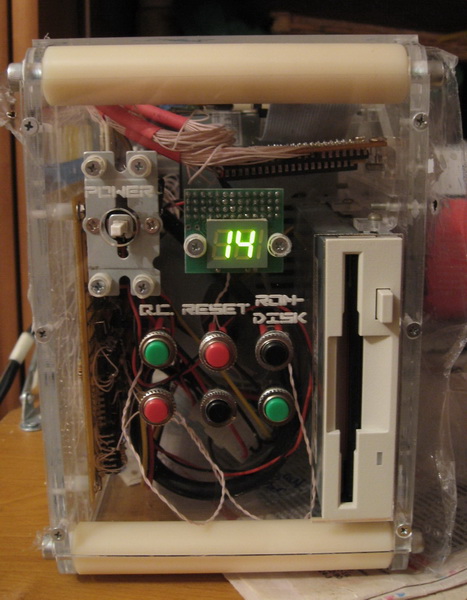
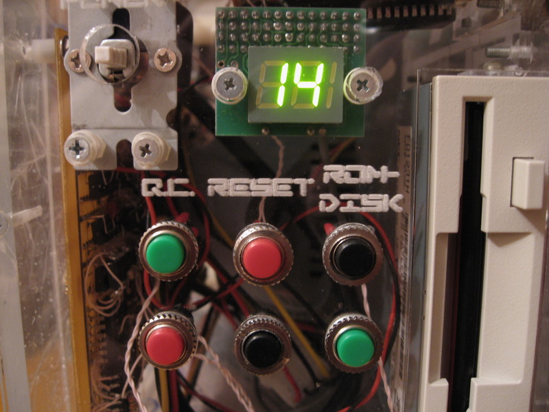
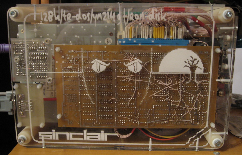
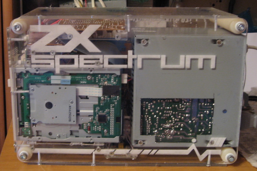

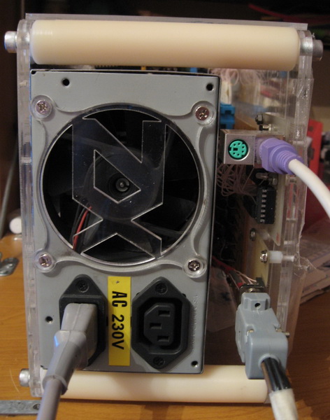
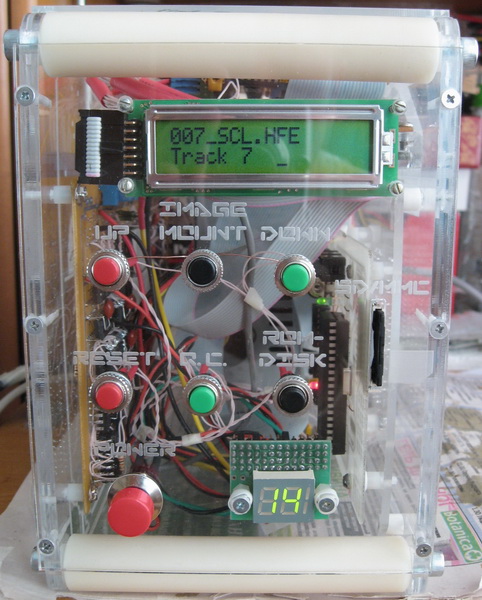
The new final front front panel of my Spectrum. It was cut on a German machine for laser engraving and cutting. You can compare with the previous one, cut on a Chinese machine - the difference is striking. The 3.5" drive was replaced with a drive emulator. In addition, I also replaced the AT feeder with an ATX one, put a beautiful big red power button with a shiny rim, with fixation. It closes the green wire and any of the black ones to start the feeder. We take the wires from the feeder connector that is connected to the motherboard of the PC computer.
That's all about the computer "Leningrad-2" No more news for today.