Nixie Tube Preamp |
RU |
Volume controller ver.1.0
A year and a half has passed since the idea of creating this pre-amplifier came to almost complete device. And now, when everything is almost already assembled and installed in the case, the wires are laid and there are not many left, I ask myself - knowing then what I started doing, would I make it or not? The answer is complex and ambiguous - yes, but I would do something a little bit wrong. The experience and knowledge gained during the manufacturing process is very significant. Also, a couple of lessons learned from the experience gained will not let you forget about yourself for a long time. Acquaintance with the right people (in terms of where to get something cheap or free) also took place, and it turned out to be very useful.
I already have a final amplifier, WP2006 in full configuration. But there I have preamp - VC PGA2310 + passive Matyushkin tone control. All in one building. It sounds just great. Two years ago, when assembling the WP2006 with the preamp in the case, I figured that it would be necessary to make a separate preamp. In the course of making the preamp, I sketched a schematic of a hybrid power amplifier with MOSFETS at the output - after the preamp I will assemble it if I don’t come up with something original.
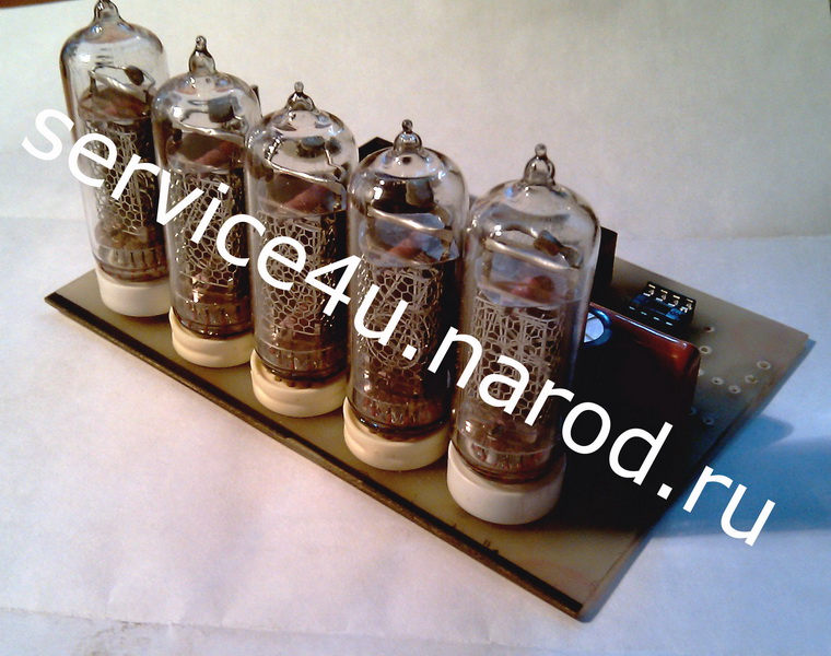
What should it be - a pre-amplifier? Matyushkin's passive tone block, which attenuates the signal by 15 times, and therefore - a buffer for raising the signal level to normal, a volume control on the relay, you can use one by Nikitin, a level indicator and a headphone amplifier, and the case will only be made of metal (not from textolite, not aluminum, no. All metal! What to use as indicators of volume, position of tone controls, inputs? You can 7SEG, LED, large or small. Come on, fuck them - you won’t see anything on small ones, but I still don’t like big ones, clumsy ones. LCD maybe? 2-line, 4-line or even graphic? No. I do not want. Thinking about the indication and rummaging through the Internet, I came across links to, as it turned out later, a very popular thing in the West - Nixie Clock. Our IN tubes were used as indicators - IN-8, IN-8-2, IN-12, IN-14, etc. I assembled watches on IN-12s for testing. In general, I really liked the way it looks. So - the indication will be done with tubes. As a VU meter, I decided to use the IN-13 - they will fit very well with the IN on the front panel. And since such a booze has gone, the buffer will be a tube one, and the headphone amplifier will be a hybrid one.
How justified is the design and manufacture of such a device at home? If you want to have at your disposal a more or less exclusive device. After reading all the material, you yourself will have to answer this question.
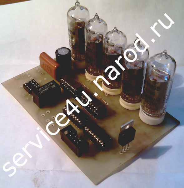
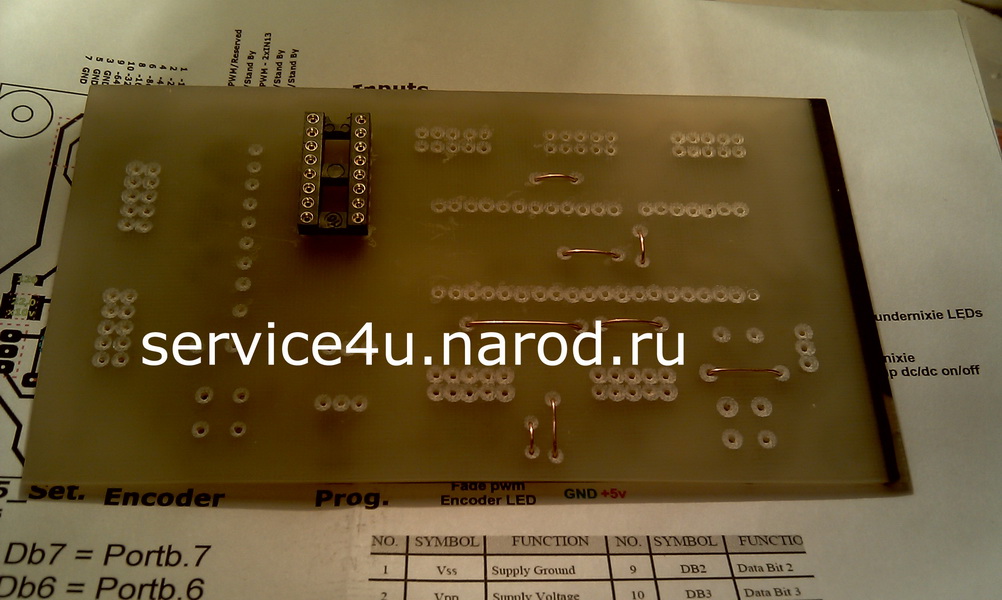
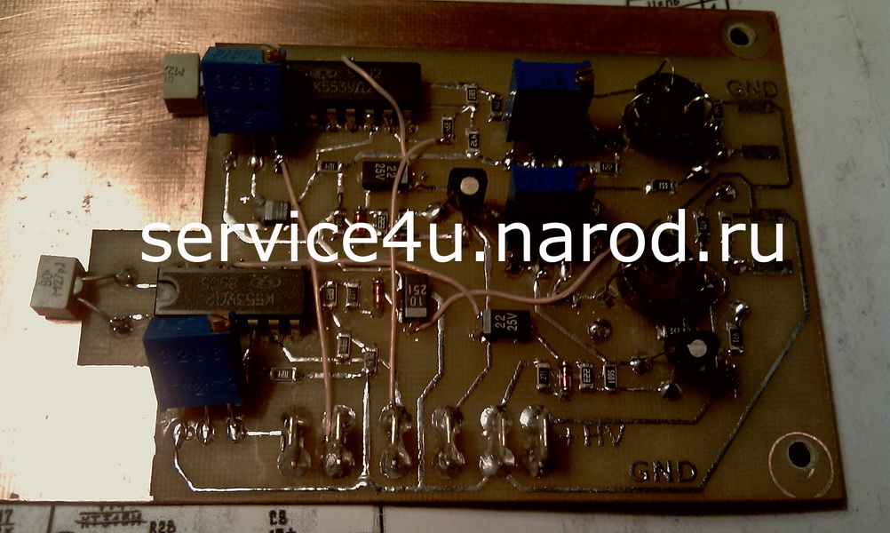
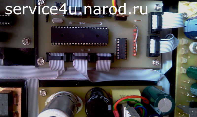
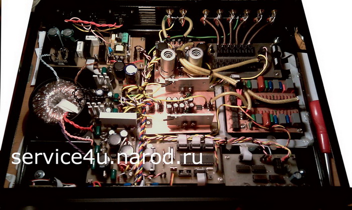
I started with the digital part - managing everything and everything. A test version of the signet was made, to fill your hand, so to speak, and indeed to check how the idea is workable and how easy it will be to implement this all. Below in the photo is the first version of the control board on tests - I did NOT leave all the materials of intermediate (not final versions) boards. The page contains materials as they appear in my life, and the final versions of the boards and circuits as well. For example, I’ll say: I redid the power supply board (rewired) 4 times, the controller board - 3 times, the headphone amplifier board - 5 or 6 times (due to listening to various circuit implementations), the indicator board - 2 times, the duty board - 2 times same way. In addition, several variants of tube circuits (voltage amplifier) were collected and listened to, as well as with their (tubes) participation in various inclusions for a hybrid headphone amplifier. You may have a question: what did the author do for so long with this piece of iron - a year and a half? I will say this: of the ready-made schemes, there was only a VC scheme, there were no other schemes. They had to be found somewhere, assembled on a breadboard, listened to, pumped, adapted to their voltages ... Each of the options for a headphone amplifier with and without tubes was listened to for about 2 weeks. As well as tube buffers with passive preamp.
For a long time on this page from the moment the design began and the hardware implementation started, there was a lot of material - there were pcbs, their photos, and indeed a lot of things. Now, before publishing the final material, I have removed all these boards and wiring. Finally: there will be no pcb here. It is enough that there are schemes. Whoever needs it - will route the pcb himself.
Perhaps someone will want to repeat the scheme of the preamp in whole or in part. Maybe when repeating one or two pcbs, yes, there will be no problems. But all before completely - this requires a kind of heroism, perhaps self-denial.
So... The very first version of the controller board was too big, not optimal, and after testing and debugging the firmware it was soldered - well, of course, I did it purely to make sure that the idea was quite feasible. In its place came the printed circuit board of the new, second version - (VC ver. 2.0). But not the last.
The scheme has undergone fundamental changes - as a result, a three-board version of the regulator - controller board + relay board + indicator board. The firmware was almost completely rewritten again due to a completely different circuit implementation. During the tests, some pcb were added, something changed, something was fixed, etc.
What the controller can do:
- volume control 0dB...-127dB
- switching inputs (1...6)
- passive preamp control (+5,10,15,20dB for LF and HF independently)
- adjusting the brightness of the indicators IN-14, IN-19V
- adjusting the brightness of the IN-13 signal level indicators
-MUTE/unMUTE
-on/off
- mode -20dB
- training IR remote control standard RC5
- leaving MUTE and exiting MUTE is smooth, when turned on, the volume level rises smoothly to the previous level that was before turning it off. When turned off, the volume smoothly decreases from the current value to -127dB.
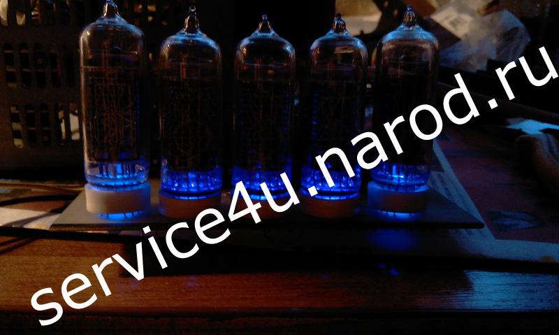
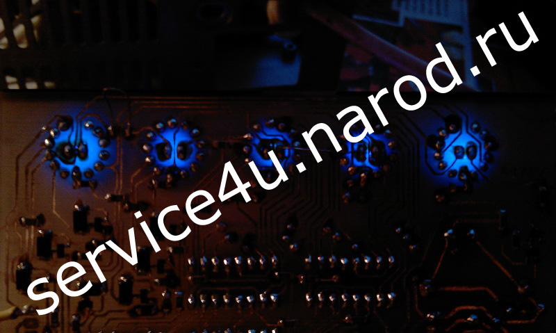
- LED illumination of IN-14 and IN-19V from the bottom of the tube.
- LED illumination of the encoder handle
- smooth change (PWM) of LED backlight brightness in MUTE0 mode
- direct input of the volume level (DVI) using the numeric keys of the IR remote control
Control is available both from the RC5 remote control and encoder.
Volume control Nixie VC ver.2.0
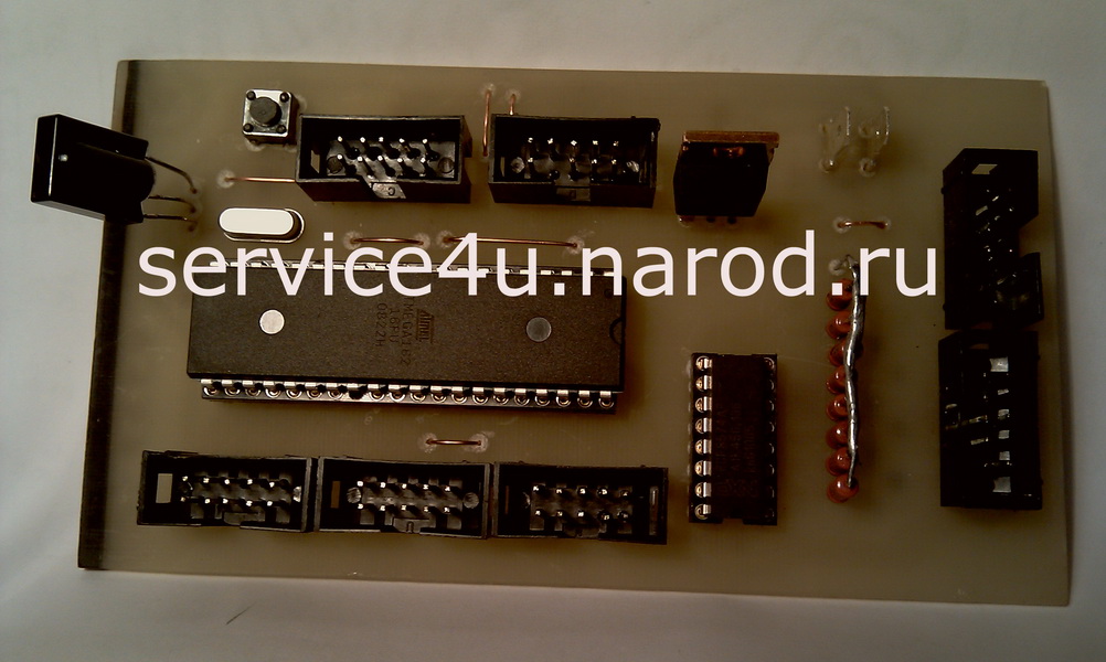
Generally speaking, the LCD version is a side-product, it was not originally planned at all, because the LCD does not fit into my design. After the chassis is ready, all these "colored bulbs" will be soldered, the board will be thoroughly washed, a strictly Nixie version will be flashed and that's it. And at the same time I redistributed it again, changing something. The final version of the indication boards and the controller board is below. These are the boards that are installed in my case. The transition to version 3.0.F (final) was facilitated by an accident on the test - I mixed up the wires + 5V and + 180V. Moreover, before switching on, I checked it three times, confirmed my mistake three times (did not notice that I mixed up the wires) and plugged it into the outlet. In M162, only PORTB.X burned out, and then not the entire port, but only one bit. PCF8574AP covered all three. KM155ID1 both survived. It became clear - the 3rd version of the control board is inevitable. PCF8574AP must be ordered, and this is 14 days to wait. Neatly and a new scarf will be ready, moreover, both the controller board and the display board. I redistributed the display board by removing the boost converter from + 15V to + 180V. I removed it because the noise of the converter was audible to the naked ear at a distance of a meter from the board, but I don’t need this. Moreover, in the Nixie Clock, which I soldered earlier, the same converter is installed, but it does not make noise at all, but for some reason you can clearly hear how it "works". Although the components in both converters are installed the same, the board for the converters is the same, well, perhaps the difference is in the coil, although they are the same. Yes, perhaps this noise will not be in the audio path, but even if so, then I don’t need some kind of buzzing-rustling from the side, everything should be quiet! and not only in the audio path, but also outside! In the final version, on the display board, I changed the LEDs for illuminating the IN-14 and IN-19 tubes from purple to yellow.
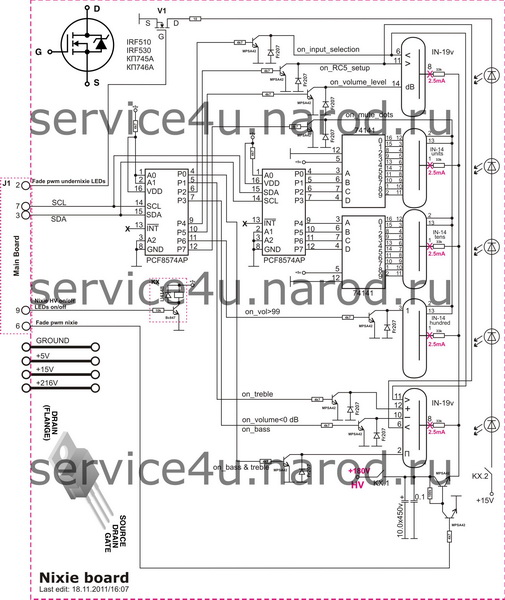
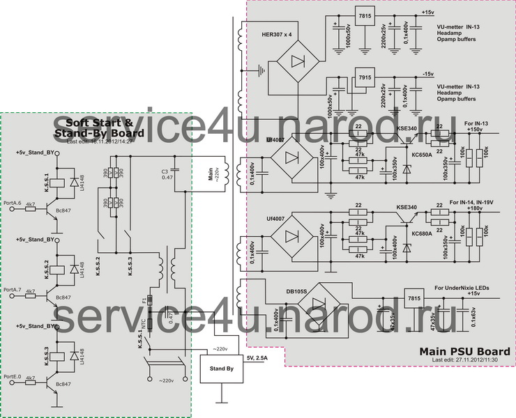
The final circuits for the Nixie version are shown below in the photo.
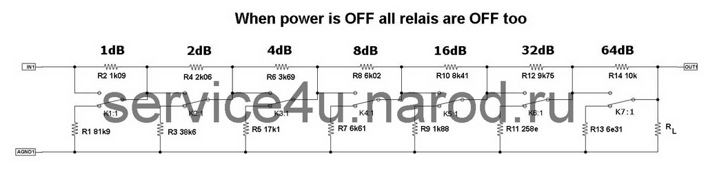
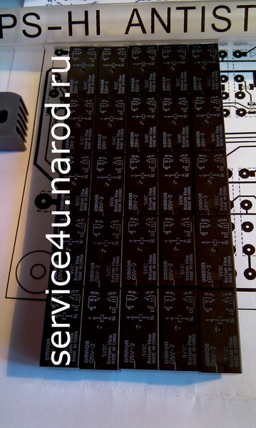
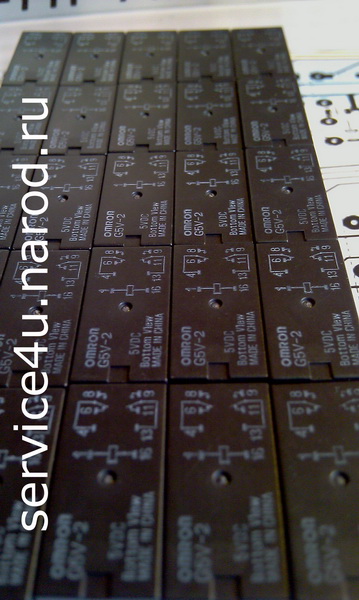
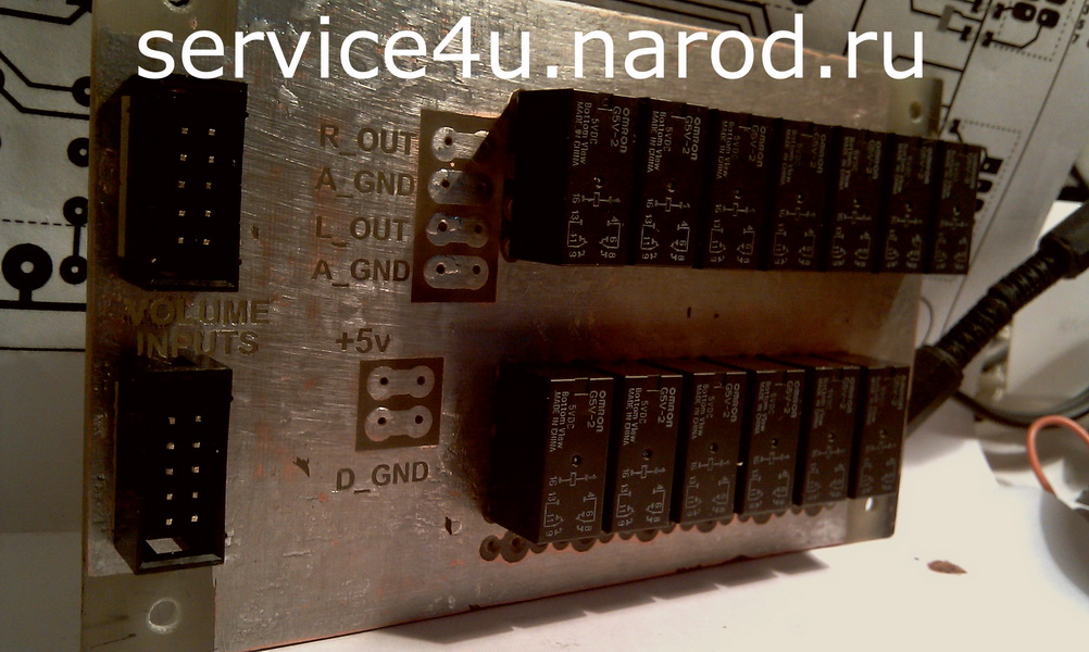
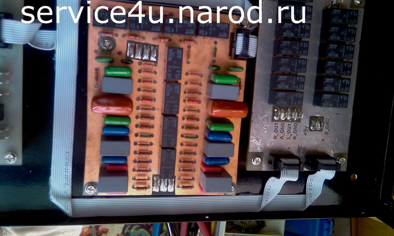
OMRON G5V-2-5VDC. I managed to get 25 pieces at the right price. All the volume control boards are soldered and almost everything has been checked, I even listened to how it sounds and how the relays switch, it's interesting, however ... This board turned out well the first time, I didn't have to rewire.
All R/2R SMD resistors on the board are 0805, the rest are 1206, diodes are LL4148, transistors are BC847W-C.
This volume control, more precisely, this method of volume control is widely known on the Internet.

Tube Preamp
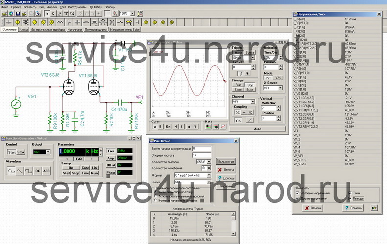
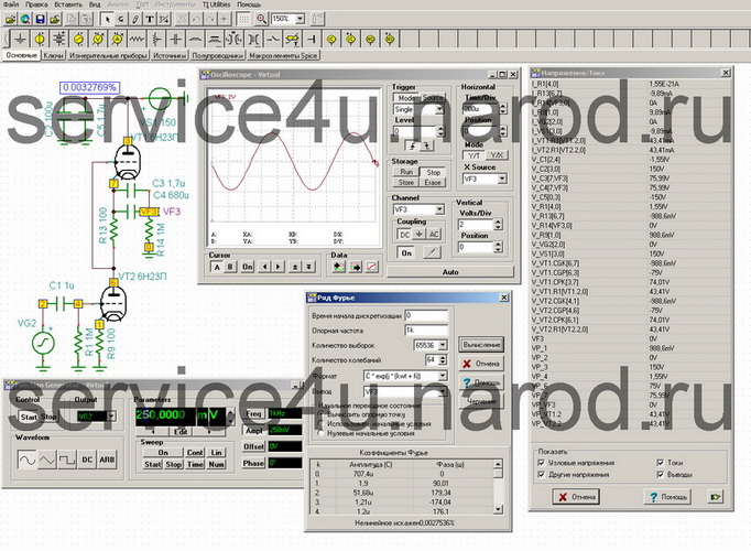
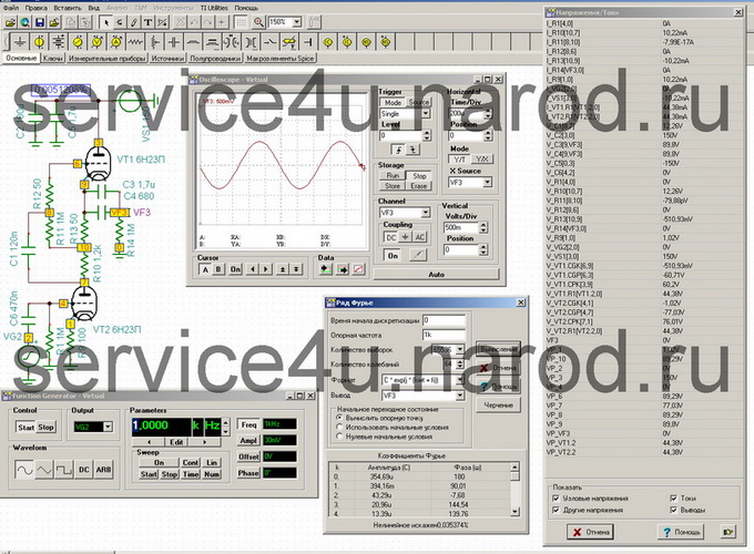
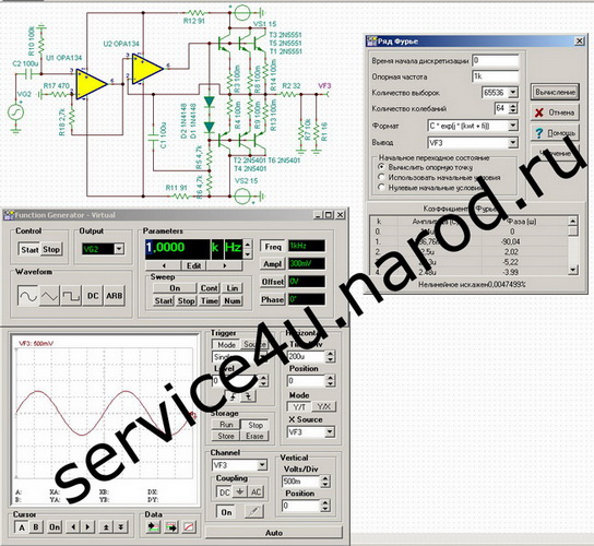
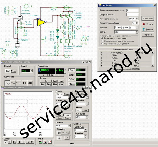
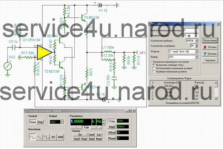
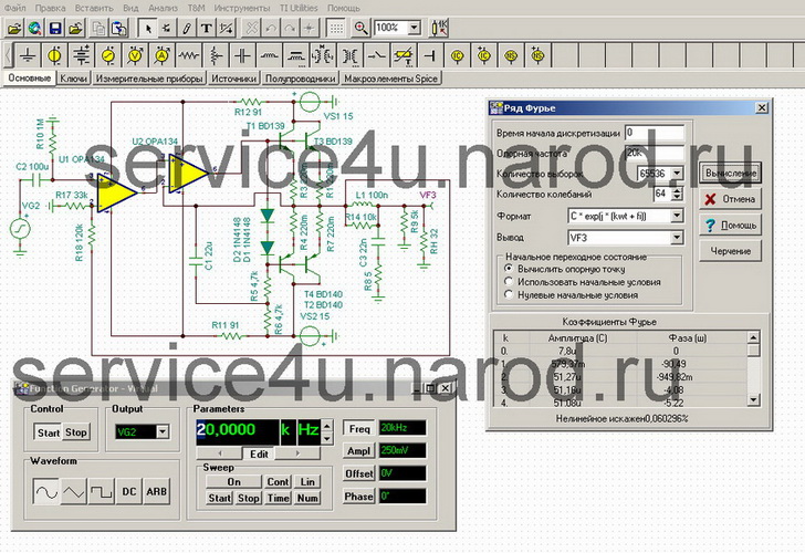
And here I don’t even know how to present the accumulated material. But I'll start. To begin with, I will give the well-known circuits for switching on tube triodes, between which I chose. So...Of the above 5 patterns, I listened to 1, 3, 5 (left to right). In terms of sound, I liked medium, 3rd. It sounds as aggressive as possible, with wild pressure, in general, not bad. But on the other hand, there is nothing so memorable in the sound. Although I remember her. The screenshots show data from the TINA-TI emulator. It can be downloaded for free from http://www.ti.com. You can read about how to work in this program in two articles written by me, where I briefly outlined the main points for working in the emulator. You can download articles here: Part I and Part II.
At the beginning, there were output elements, so the test boards were bred for two-watt MLTs and for 400V and 630V conduits - they turned out to be large and bulky. After, I used SMD2512 (1W), the maximum voltage for them is 400V, the nominal voltage is 200V. My anode was 150V, so we fit in.
After there was another buffer, after it - another one, and another one.
1
2
3
4
5
After that I also listened to Aikido. I think everyone has seen this schematic. There the author used 6H8C and 6H9C. You can find the scheme yourself by its name.
"There is nothing to write about tube boards yet and I won't give a diagram yet, because I haven't listened to it yet. Perhaps I'll unsolder all these tube boards and throw out-put a few opera- and ok" - remember this place in the epic, we will return to it later (Flashback). I wrote this proposal here a very long time ago, long before I started listening to the circuits and long before putting the boards into the case, and the case didn’t smell even close then. And then I wrote: "Maybe I'll leave the tubes, but I'll put 6N8S, 6N9S, for example, because I heard these tubes how they sound, but 6N23P I don't know how they will sound. Or maybe I'll use something else - I don't know bye."
Aikido sounds amazing! It would be more correct to say that in Aikido the 6H8C tube sounds. Yes, I tried 6H8C just in a voltage amplifier, in SRPP and in a cathode follower as well, I noticed a long time ago that 6H8C sounds completely different from, for example, any of the tubes: 6N1P, 6N2P, 6N23P, 6N24P. I liked it less in the cathode follower, in SRPP its sound is somehow more pronounced. I also tried it in Aikido, changed 6N9S to 6N2P to get more gain, put a current amplifier on the output and make ULF for headphones. But more on that later...
I used all new tubes. And, of course, before the first full-fledged use of the radio tube, I performed the following steps: we take the tube out of the package, connect ONLY the filament terminals to the power supply with adjustable output voltage. I changed the output voltage within 1V ... 6.3V, and the time during which the voltage should rise from 1V to 6.3V was 7 days. I added about a volt per day. Further, with a heating voltage of 6.3V applied, I applied half of the anode voltage (for 6N24P it is 45V) to both triodes and kept it under these conditions for a little more than 2 hours. Further, I increased the anode to 90V and a little more than 2 hours. When carrying out these physiotherapy procedures, all other outputs of the tube hang in the air. After such a massage, the radio tube is ready for its intended use.
On the board, you can see the presence of a seat for the SMD resistor, but in the final version, after listening, a jumper is installed instead. Why? When I listened to this buffer at the prototyping stage, an excitation or subexcitation was detected, and there was no excitation only in the very extreme position of the HF tone control, i.e. there is no excitation in the maximum position, and three positions of the relay below the maximum - there was excitation. 47 ohms into the gap solved this problem at once. When all the elements moved to the printed circuit board, the excitation disappeared, and the space for the resistor remained. Therefore, there is now a jumper.
PSU
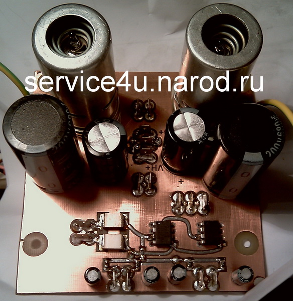
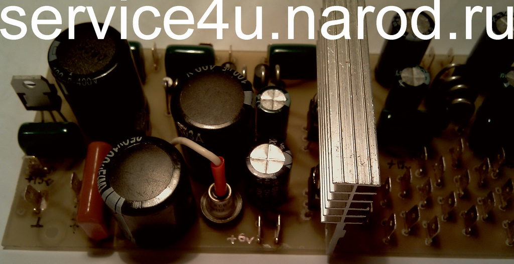
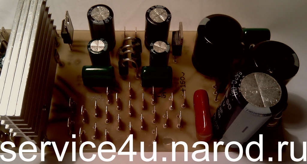
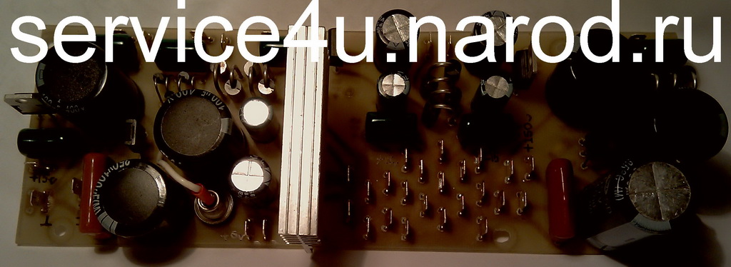
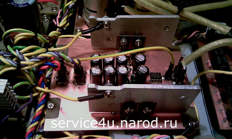
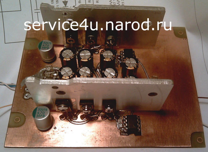
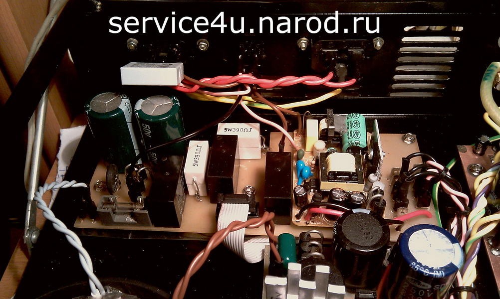
At first there was an impulse switch on the SG3525 + IR2110 with current protection. I will not give the circuit and the board here, the Internet is full of versions. There were no stabilizers on the impulse board, I made them on an additional board. Power in standby mode, I "performed" the type of power supply from the print server D-link DP-301U, 5V, 2.5A. Small and appropriate. It provides power in standby mode and in working mode as well. The photo below shows the final version of the stabilizer board.
A few words about how and what the preamplifier is powered by. It can be seen from the stabilizer diagram that I used a series-type compensation stabilizer for supply voltages of + 150V (IN-13) and + 180V (IN-14, IN-19V). Serial because the regulating element (in the circuit it is a high-voltage transistor) is connected in series with the load. Capacitances there will not hurt, the more - the better, well, and think about the voltage reserve for which the capacitor you are installing is also designed to not hurt. Therefore, I applied capacities for 400V and 350V. The backlight LEDs are powered by ST7815A (+15V), bipolar 15V each is powered by stabilizers of the ST7815A and ST7915A series.
IN tubes power supply can be organized in different ways. The schematic for the Nixie version shows a boost converter. Initially, I used it, but subsequently unsoldered it and further excluded it from the circuit. On the board with IN tubes, an empty bed from a DIP8 microcircuit and several empty holes are visible. After, I soldered an ordinary feeder with several anode ones for everything: I have IN-14, IN-19V, IN-13, 6N24P there. The consumption currents are not very high, so everything fits on the torus with a margin. The torus is wound by hand with repeated impregnation of each layer with varnish, followed by drying. Thor is applied with a ready-made primary impregnated and thoroughly varnished. Well, I wound up the primary - I threw another 150 turns. Got 5.9 turns/volt instead of the initial 4.88 turns/volt. The windings for powering IN-14, IN19V and IN-13 are wound with a wire with a diameter of 0.22 mm along the varnish. The winding for the LED illumination INok is wound with a 0.4mm wire over the varnish, each of the +/- 15V windings is wound into two cores of 0.56mm each with a diameter of the varnish. The filament winding is wound with a wire with a diameter of 1.22 mm over the varnish. Thor was taken large in order to fit all the windings. Each winding is insulated with lavsan from a flower shop. The primary is isolated additionally. Where to get lavsan? There are flower stalls near the house in the subway passage, we go to the sales girls and ask them to sell you, but not lavsan, but "that cellophane in which you wrap the bouquets." For 10 cents, he buys several sheets from them about 1m x 1m in size, you can even take them in circles, beans or stars, so that the inside of the device would be more fun for the torus after the case is tightly closed. Do not take a shiny one, like a mirror one, you know why.
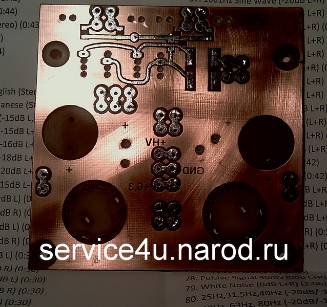
power sypply
power supply. pcb
power supply. ground
power supply.
Power supply for IN-13 and 6N24P tubes is standard, compensated voltage regulators. The diagram above is shown.
When using the LCD version and in the absence of IN-13s, nutrition issues are greatly simplified.
Well, fans of the use of pulses in audio technology (yes, there are plenty of them too) can try to power all this through a pulsed power supply. I also tried, but more on that below.
VC LCD ver.2.0
- volume control 0dB...-127dB
- switching inputs (1...6)
- passive preamp control (+5,10,15,20dB for LF and HF independently)
- LCD backlight brightness adjustment according to RC5
Perhaps there will be a version of the firmware in which the backlight slowly goes out (Fade-out) after a while in the absence of commands from the IR remote control and in the absence of commands from the encoder - this option has already been implemented and tested.
-MUTE/unMUTE
-on/off
- mode -20dB
- training IR remote control standard RC5
- going into MUTE and exiting MUTE is normal, when turned on, the volume level takes on a fixed value, set in the firmware at startup. When turned off, the volume takes on a value of -127dB.
- LED illumination of the encoder handle
- smooth change of LED backlight brightness in MUTE mode
Control is available both from the RC5 remote control and encoder.
In LCD version 2.1, the backlight of the display will slowly turn off on its own when there are no commands from the remote control and if you do not use the encoder. This firmware version does not have the ability to control the brightness of the IN-13.
- on/off
- Mute
- volume "+"
- volume "-"
- inputs "+"
- inputs "-"
- bass "+"
- bass "-"
- treble "+"
- treble "-"
- "-20dB"
- backlight "+"
- backlight "-"
In LCD-version 1.1, the backlight of the screen does not go out at all, but the backlight level can be adjusted from the remote control from 0 (completely off) to maximum (the brightest).
- on/off
- Mute
- volume "+"
- volume "-"
- inputs "+"
- inputs "-"
- bass "+"
- bass "-"
- treble "+"
- treble "-"
- "-20dB"
- LCD Backlight "+"
- LCD Backlight "-"
- led "+"
- led "-"
- brightness ИN-13 "+"
- brightness ИN-13 "-"
In LCD versions device configuration is almost the same as on this amplifier page in the "Volume control" section. Absolutely everything is transparent and without problems - you just need to solder the Main Board, connect the LCD, apply power and flash the MK.
Smooth exit to Mute and exit from Mute left. I spread the schemes and firmware of various versions. Welcome!
Added ON / Stand By signal processing on the PortE.0 port of the mega. I will solder the connection to the board and output it with a cable with connectors neatly to the PSU board to turn on the main transformer (Main) through a soft start. I have already made changes to the scheme. The circuit and power supply boards will be below.
: : Nixie_version : :
: : LCD_1.1 : :
: : LCD_2.1 : :
Исправлен баг отображения колбаски на LCD при регулиревке громкости.
И еще что-то исправлено и добавлено. В результате две опциональные прошивочки.
: : LCD_1.10 : :
: : LCD_2.2 : :
How it works
First, decide which version you are going to make. The LCD version consists of a main board, an R/2R board with a relay + a relay for switching inputs, and a tone block board. For the Nixie version, another board with INs is added, but the LCD is excluded. Next, we make the main board, solder everything. Connectors for the Nixie board, for the tone block and for R / 2R can not be soldered, this can be done later. pcb soldered. If you will route the boards yourself, then you yourself will be able to arrange the bloks "to your taste".
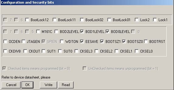
We flash AVR ATmega162. We set the fuses as in the previous screenshot.
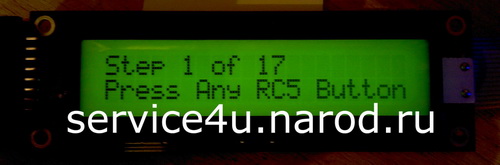
After the first power supply for the LCD version, a message will appear on the indicator screen asking you to press any button on the IR remote control to determine whether the protocol is RC5 or not. If the IR remote control is RC5, then we go to the command configuration mode and messages will appear on the LCD asking you to press the buttons on the RC5 remote control. After configuring the device, the programmed buttons are checked - the name of the RC5 command and the code corresponding to it will appear on the indicator screen one after another. All codes of the pressed buttons are recorded in the EEPROM of the AVR. After that, the power of the device should be turned off, you will see the corresponding inscription on the LCD screen. The next time you turn on the device, the volume level is set, the first input is selected, for the passive tone block, the frequency response level is set to +5dB for low frequencies and +5dB for high frequencies.
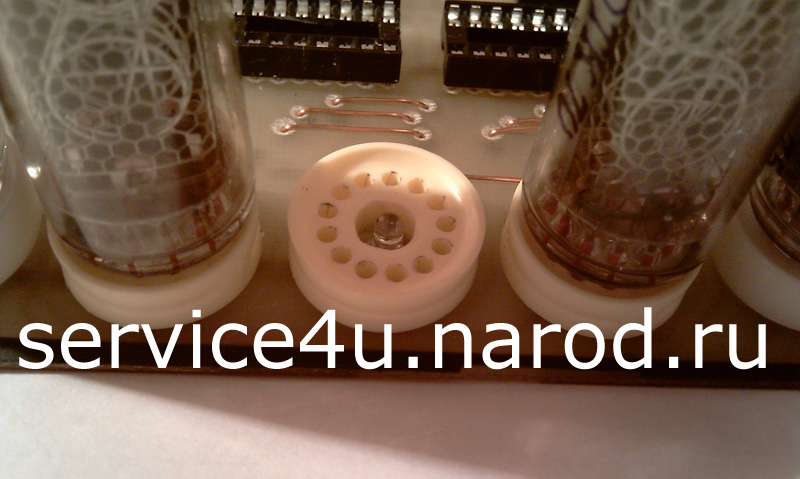
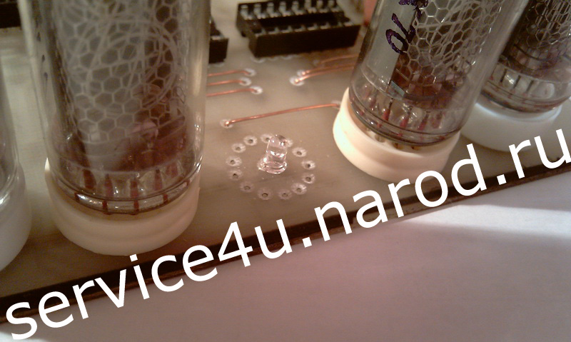
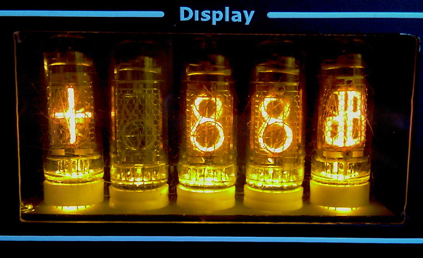
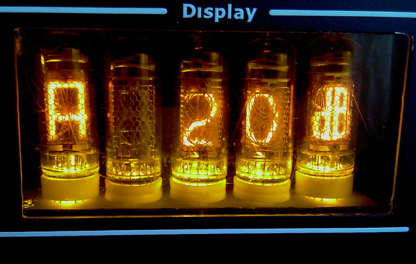
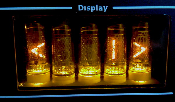
There is no LCD indicator in the Nixie version, but the principle is the same. After the first power-up, the dots in the three middle IN-14 tubes begin to blink, as in this photo. This means that the device is waiting for any button on the IR remote to be pressed to determine if it is RC5 or not. If the IR remote control is RC5, then we switch to the command configuration mode, and numbers appear one after another on the IN-14 tube. After the appearance of the digit, press the button on the IR remote control, the command is remembered and the next digit appears, etc. until all commands have been programmed. The sequence of commands (the appearance of numbers) is as follows:
- while the IN-14 dots are flashing - press any button on the IR remote control
- 1-on/off
- 2-Mute
- 3-volume "+"
- 4-volume "-"
- 5-inputs "+"
- 6-inputs "-"
- 7-bass "+"
- 8-bass "-"
- 9-treble "+"
- 10-treble "-"
- 11-"-20dB"
- 12-brightness ИN-14 "+"
- 13-brightness ИN-14 "-"
- 14-under nixie leds ИN-14, ИN-19В "+"
- 15-under nixie leds ИN-14, ИN-19В "-"
- 16-brightness ИN-13 "+"
- 17-brightness ИN-13 "-"
After entering the last command, you will see a jumping zero on the IN-14 - turn off the power. After the next power-up, a fade-in is performed, i.e. the volume level smoothly increases, stops, input 1 is selected, for bass and treble frequency response is set at +5dB.
Any of the versions provides the possibility of forced configuration of the AVR to work with the IR remote control. To do this, BEFORE applying power to the board, press and hold the button on the "Manual RC5 Setup" diagram. Thus, after applying power, you get to the very beginning of the RC5 command configuration menu, and you will have to do the whole procedure again. Once the procedure has started, the "Manual RC5 Setup" button can be released.
How to control
In any of the versions, the encoder executes the following commands:
- in the off state, holding the encoder button for a long time (more than 3 seconds) turns on the device;
- in the on state, holding the encoder button for a long time (more than 3 seconds) turns off the device;
- in the on state, holding the encoder button for about 2 seconds. causes the Mute command to be executed;
- exit from Mute is carried out by arbitrary rotation of the encoder knob in any direction or by holding the encoder button for about 2 seconds.
- after the device is turned on, the rotation of the encoder knob leads to a change in the signal attenuation level;
Navigate through the menu items by briefly pressing the encoder button, while the order of menu items for LCD versions is as follows:
- input selection;
- frequency response level of LF;
- level of frequency response of HF;
- signal attenuation level (volume control);
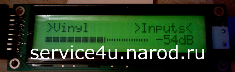
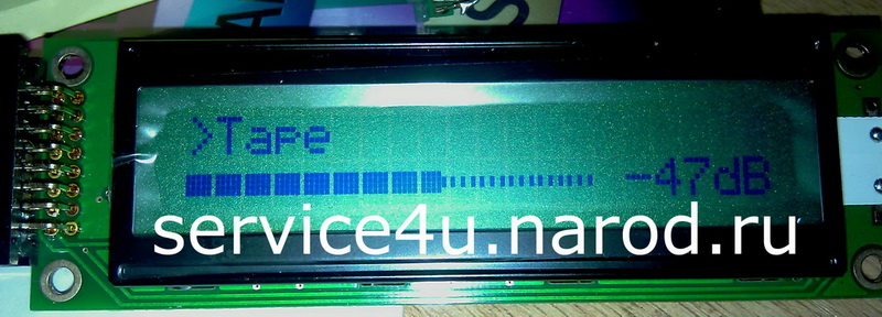
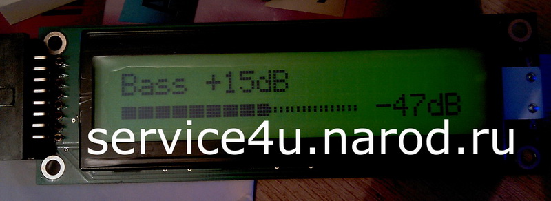
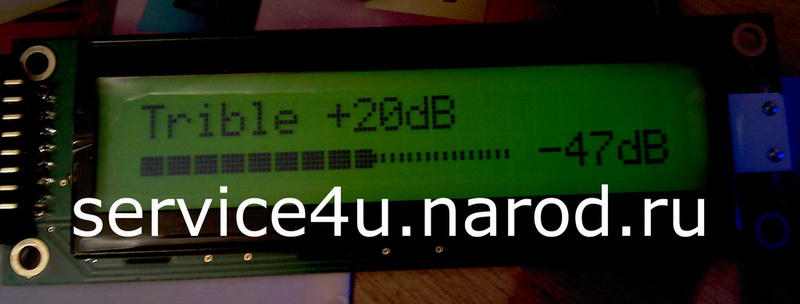
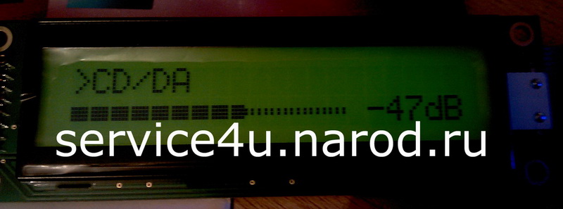
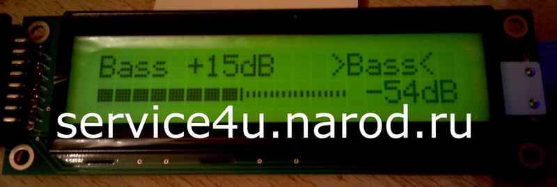
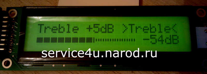
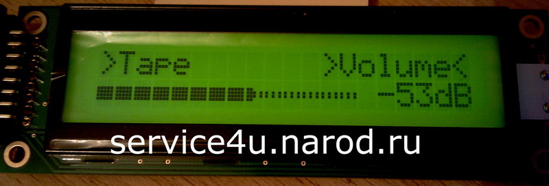
In this case, when moving to the next menu item, the name of the current menu item is displayed in angle brackets ">.......<" in the upper right corner of the LCD in angle brackets ">.......<". If you press the encoder button and do not rotate the encoder knob for about 3 seconds, the device returns to the main menu - signal attenuation. Being in any menu item and provided that the encoder knob does not rotate for about 3 seconds, the device goes to the main menu item - signal level attenuation. After the pause in the use of the encoder expires, the inscription in angle brackets ">.......<" in the upper right corner of the LCD disappears, which indicates a return to the main menu - signal weakening.
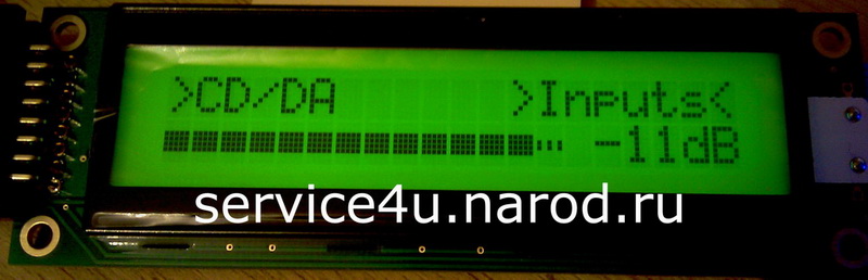
The device is also controlled by an IR remote control in RC5 format. Direct commands are executed from the remote control.
In the Nixie version, everything is about the same as for the LCD version, but much more aesthetic and pleasing to the eye.
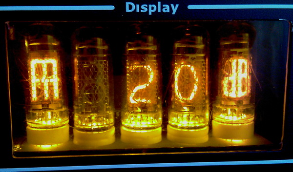
From left to right: frequency response boost +5, +10, +15 and +20dB, signal attenuation level display, input selection. The only caveat in the Nixie version is that there is no difference in the display of the frequency response adjustment for bass and treble. But everything is simple here: the menu switches only in one direction, in a circle, so immediately after the volume - the input selection, the rise in the frequency response for low frequencies, then - the rise in frequency response for high frequencies, well, etc. and the same way in the opposite direction.
The full menu in the Nixie version has the following sequence: volume, inputs, bass, treble, brightness IN-14, IN-19. In the IN-14, IN-19 brightness control mode, "+88dB" is displayed on the tubes for clarity and completeness of sensations.
If the device is in Mute'e and you turn off the power, the volume level is set to the minimum (-127dB) and the device turns off. When you turn it on again, the volume level remains "-127dB".
And now about the most useful and practical mode - DVI - Direct Volume Input or direct input of signal attenuation level. Literally 1 minute after adding it to the firmware, I realized that this would be the most popular (because practical) mode. Everything is simple here. To enter the volume level (signal attenuation level), I use the number keys on the IR remote control. We enter the numbers of the desired volume level in dB in the mode of displaying the volume level on the indicators. A couple of examples: I want the volume level "-101 Db", so I press the buttons on the remote control: 1, then 0, after 1. After pressing the third key on the remote control, the volume level is immediately set in accordance with what I pressed, namely "- 101 dB". When entering numbers, they appear on the IN-14 from right to left all together as you press the buttons on the remote control. In the same way, we enter a two-digit signal attenuation level. One caveat - after entering the second digit, the volume level does not change immediately, but after about 1.5 seconds. And after entering a one-digit attenuation level (when only one digit is entered), the level changes after about 2 seconds. But this can be bypassed. For example, if you need to enter the volume level "-5 dB", then in order for the volume level to be set faster, you need to press 005 on the remote control, while "0" is not displayed and after pressing the key with the third digit, the volume level will be set immediately.
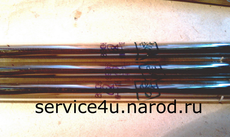
VU-metter IN-13
The level indicator / VU-metter was assembled a long time ago according to the classical scheme on K157DA1. Initially, a circuit with a half-wave detector was tried (there are a good number of circuits on the Internet), but almost immediately I abandoned it, although a unipolar supply was required, in contrast to the full-wave K157DA1, which requires bipolar voltage. Why? Simply, I read somewhere in the annotation to the VU-metter circuit on LEDs and a PIC controller: "because the positive and negative half-waves of the musical signal are the same, we will make a half-wave detector."
Positive and negative half-waves are equal, for example, near the sine, and even then, if you do not use the asymmetric limitation mode in the generator. But, generally speaking, the positive and negative half-waves of a real signal are different.
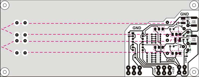
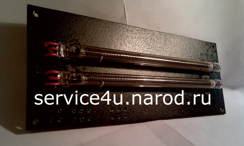
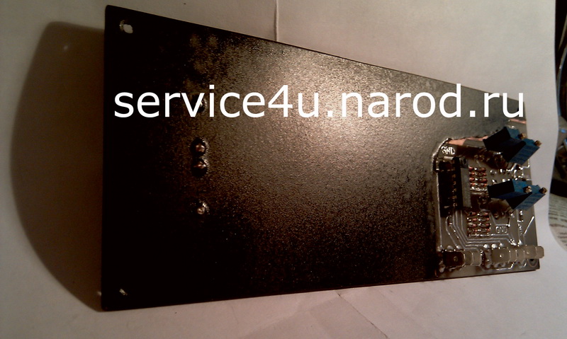
The indicator board is painted and varnished.
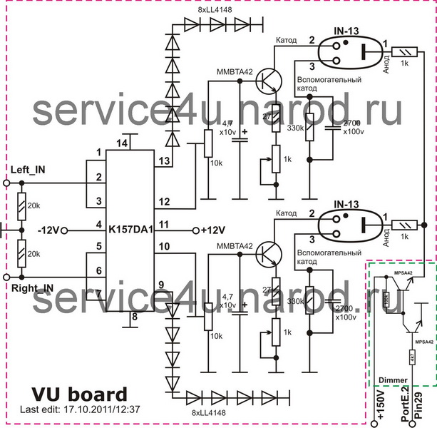
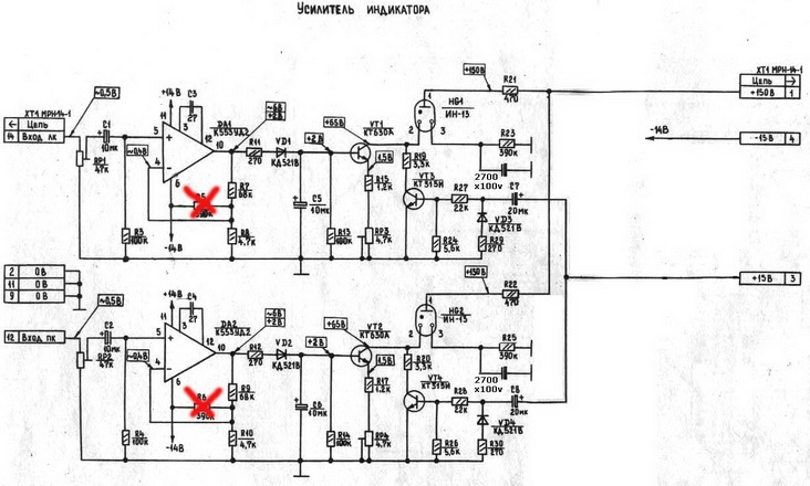
: : VU-metter / ИН-13 : :
After all the boards were installed in the case and I started testing the full audio path, it became clear that the indication circuit on the K157DA1 was not suitable for me. I took the scheme from the Olymp-004 tape recorder. Routed pcb. Soldered. Tested. No problem. The only thing I did: I removed the 390k resistor (responsible for the initial illumination of the beam from zero) and put one 2700x100V capacitance each (indicated in the diagram). The indicator board is degreased on the outside and pasted over with a black film for plotter cutting.
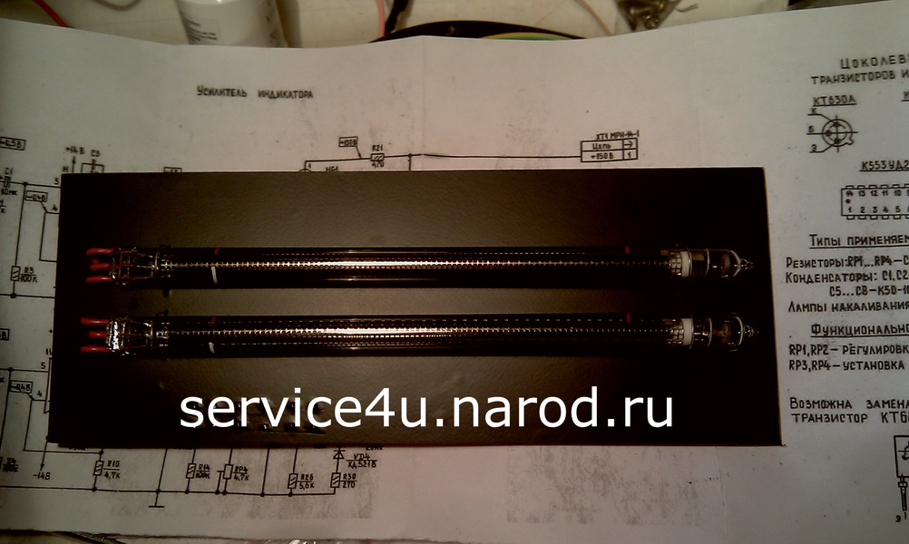
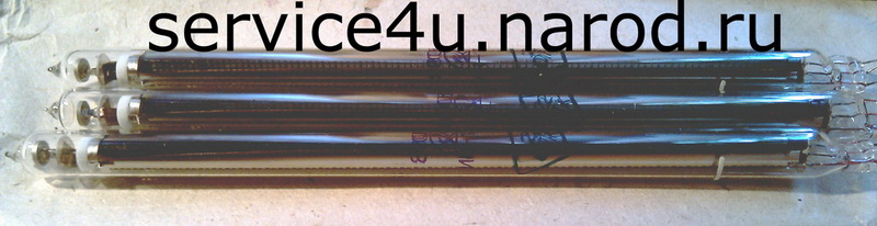
Due to the narrow dynamic range of the IN-13s, they perform only one task - they show the presence of a signal and its level at the preamplifier inputs.
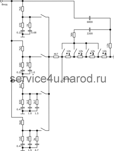
Passive Tone Board / Bass, Treble
I will again use the before according to the Matyushkin scheme, more precisely, only the corrector for bass and treble. Scheme, boards, photos... But you have to be prepared for the fact that I have not yet heard how this pre-combined with tube cascades. You may have to change something, maybe resort to the Bascandall scheme. Or maybe I'll like it. As time passed, I liked the sound, the passive front remained in the path.
All work on the Preamp's chassis and body was completed. All boards have been installed. I started testing the full audio path. And here I stepped on a rake, and for children. What happened? After tubes warmed up (approximately 30 seconds), a strong hum with a frequency of 200 Hz appeared in the audio path. Strong, because the tubes caught some kind of interference and amplified. Shielding tubes did not help. The ground was NOT starred on the stabilizer board. There are no loops. Neither around the transformer nor around the boards. With the pulse generator, the problem was the same, only instead of a clear 200 Hz, a wild buzz was heard with the admixture of those 200 Hz, just wild. In both cases (pulse feeder or torus), the noise level always remained the same, even when the signal level changed. I replaced the impulse feeder of the duty room with a traditional one on the torus - the same eggs, some kind of interference brings down, and not frail, and even though you crack. I replaced the scarf with a buffer tube amplifier for the same one, but on operas - silence! You don't even know if it's enabled or not. Here you have the denouement of the plot - you will have to replace the tubes with operas. Which is what I did. I put aside the boards with tubes, took out the op-amp from the stash. And here we remember the very place (Flashback). But here, too, a rake, and again for children - first, arousal, and then, excite, but not immediately after turning on the power, but only after 5-10 minutes, even though it is an op-amp, not tubes. I tried the serial wiring of the earth - it helped, but partially, there was still some kind of excitement. It became clear that drastic measures had to be taken. After that, I redistributed the stabilizer board and re-layed the wires differently.
And now, after the correct wiring of the stabilizer board and the correct laying of the wires inside the case, all the excitations and sub-excitations disappeared, and there was real silence in the absence of a signal. Here you have the problem solved. And I went back to the tubes, replaced the board with the op-amp for a board with tubes, 6N24P. Still - the tubes don’t sound like an OU, ha. The difference in the sound of the op amp and the tubes is audible immediately after the preliminary warming up of the tubes, a couple of minutes. And after 15-20 minutes of work - tube! tubes! And more tubes! Why? But you yourself take it, solder it and listen, and all questions will disappear. And the reason was banal - incorrect wiring of the earth. Well, oh well - the problems are solved - we go further. And then there's the headphone amp...
Headphones amplifire/Hybrid, Opamp
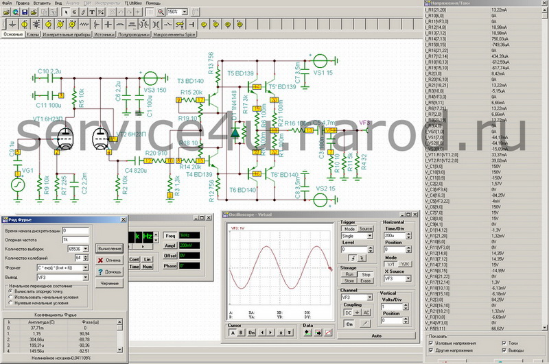
I think everyone recognized the current amplifier in the last three diagrams. Well, why not - new - well-forgotten old. Yes. 1982 however. So what. But the sound is strong. Especially with a tube preamp at the entrance, oh, how quickly it jumps! In general, there is a field for experiments. All these schemes are working. Verified.
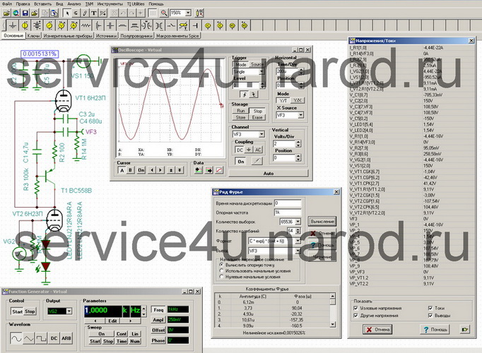
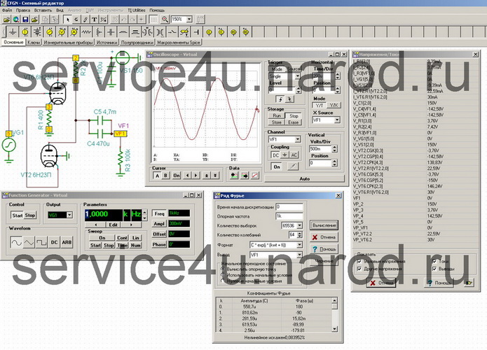
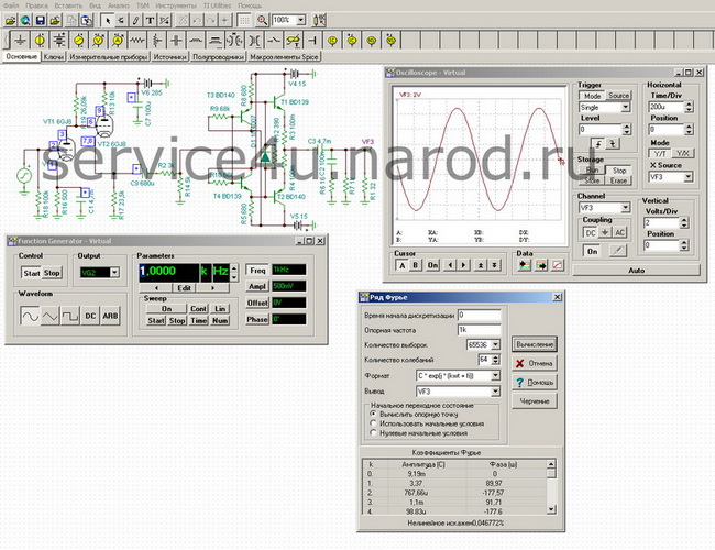
You can talk about a headphone amplifier for a very long time - many circuit implementations were listened to, both with op-amps and with tubes, they all sounded differently, and each time, after listening to one or another option, I wanted something more, better, bright. And it’s not so easy to implement an amplifier for low-impedance headphones - I have a TDS-7 (8 Ohm). With high-resistance, everything is simple - you don’t need a large swing at the output and you don’t need to drive a lot of current through the load. Here, with a resistance of 8 ohms, you will need a lot of current and voltage as well. I took one well-known circuit, tweaked it a little and now it is ready to work on a low-resistance load. It's called Lehmann. I called my version Pryanickman:
The original circuit provides 1.12V at a current of 140mA, for 8 ohms this will not be enough. Through simple and not very long tests, it became clear that I was on the right track, and in the end I finally came to the scheme that is on the far right. SOI at 20 kHz is about 0.45% at the indicated ratings on the diagram. At the output, I have 3.26V at a current of 407mA - but this is already an application for the final. And this will be a lot. That's why he and the volume control to adjust the signal level at the input. And at a voltage of 3.26V and such a high current, listening to music will not be comfortable. And therefore, I will not hear these 0.45% on the HF. I will say that the sound is just very high quality! All that's left is to change the ear pads of the TDS-7. After this replacement, their sound will improve markedly. The main thing is to know how to do it right. At the same time, we change R7 and R8 to 0.1 Ohm and at a frequency of 20 kHz the THD for the original circuit and for the circuit in my design becomes almost the same - 0.12% and 0.18%, respectively. At frequencies from 10Hz to 100Hz, everything is generally fabulous, THD of the order of 10E-005 - 10E-004, and this is our everything.
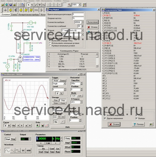
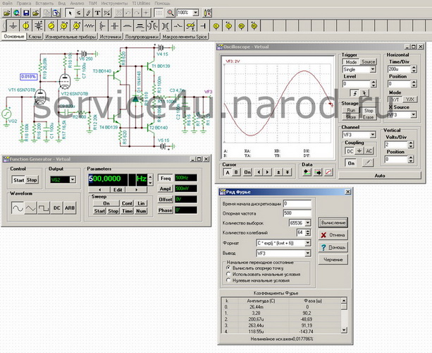
But 32 Ohm is one thing, and 8 Ohm is quite another thing. For high-impedance headphones, I can offer you this circuit:
I'll call this scheme Douglas. In the LF area, the THD is the same as that of the Pryanickman circuit, but at the HF it is much lower, in the screenshot it is exactly 0.074% at 20 kHz. THD can be further reduced by applying the OS input from the first op amp to the amplifier output. In this case, the THD at 20 kHz will be 0.055%. Doesn't sound very bad! I listened on my Fischer Audio Sigma - super sound! Bass is just very clean. I recommend. The diagram shows the output transistors BD139, 140 - you can put transistors and weaker ones, for example, 2N5551, 5401 or 2SC3502, 2SA1380 or something. I listened to this circuit performed by 2SC3503, 2SA1381. I put three pairs each, because I have a lot of these transistors - they remained from the time of the VP2006 tests, so they unexpectedly came in handy even for myself. The amplifier sings very high quality and clean.
Often on the forums, people ask for some kind of headphone amp in class A, they say in class A it sounds better than in another class and there are less distortions and blah blah blah. What difference does it make in what class the amplifier works if you have not heard it? It is clear that a person just wants to assemble the circuit, plug the board into the case and listen to music, believing that he has the highest quality VCL (or not even thinking about it). Neighbors, acquaintances, friends then come to him and, showing off to everyone, he says something like - well, well, hey, class A, ep. And just like that, the myth that class A is the most epic is dispersed. I will say this - it's all unsupported, at the level I feel the ringing, I don't know jo yon. My personal opinion - if you like the sound, and at the same time the amplifier does not play, but sings, then what difference does it make to you personally in what class it performs?

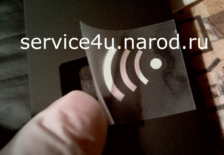
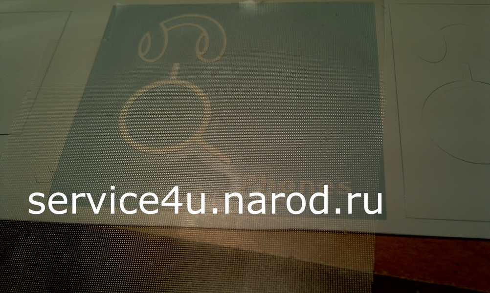
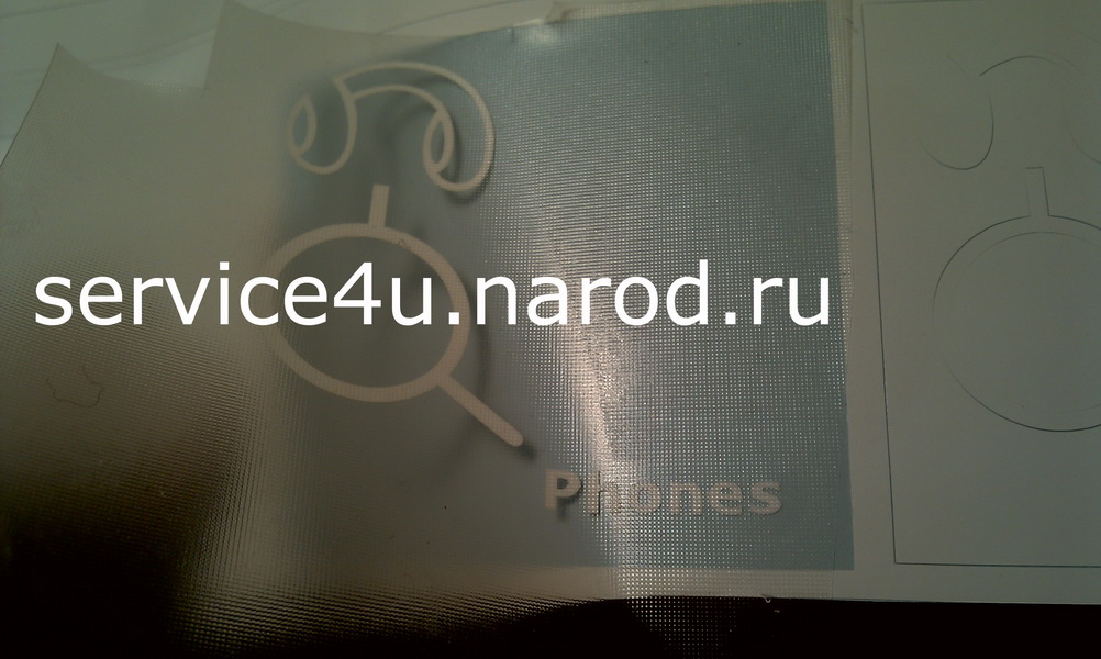
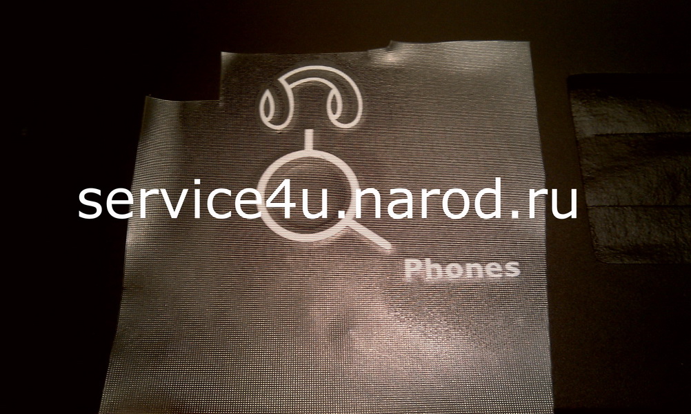
Plotter Cutter
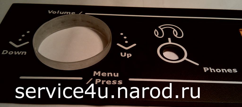
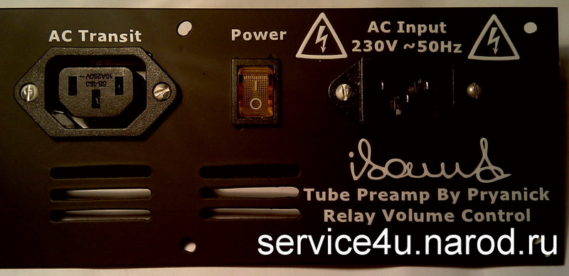
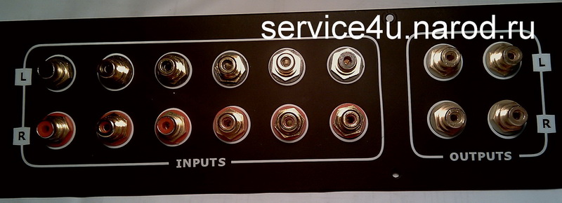
How to make inscriptions on the device panels? I made it using the plotter cutting method. There are some subtleties when creating a drawing for a plotter, but I omit them and I think that you already know everything and move on to the next phrase - after you have drawn your template or drawing in CorelDraw, you need to complete it. This is done on a cutting plotter. Cut out. We selected all the unnecessary elements of letters and other fillings, leaving only the necessary details of your drawing. With the help of a mounting film, we transfer your drawing to the mounting plate, apply the mounting plate with the pattern exactly as the pattern should be applied to the panel, apply the mounting plate with the pattern to the panel, but do not press it, but just make sure that the picture lies exactly, or as you need. And then we press and smooth. After, the montage can be easily removed and is suitable for several more cycles of transferring drawings to the panel. And the picture remains where you pasted it. And after the end of the procedure for forming the front panel, we put 2 layers of varnish. Needless to say - no fat allowed! Do not touch the painted panel with your fingers! That's why I worked with gloves.


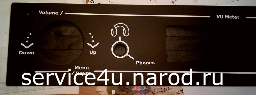
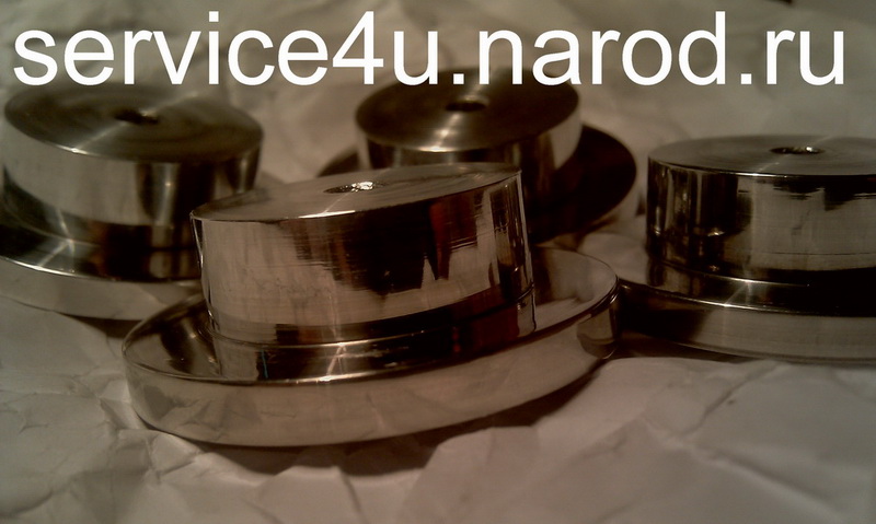
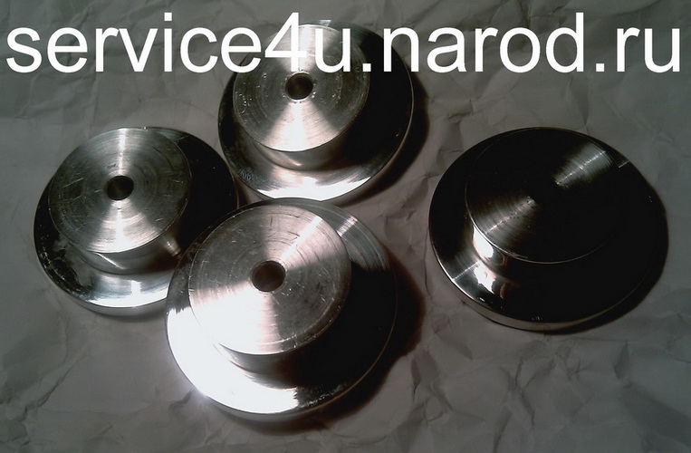
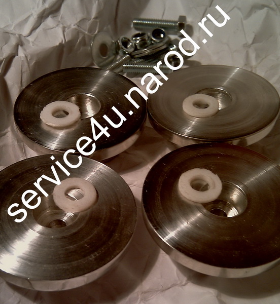
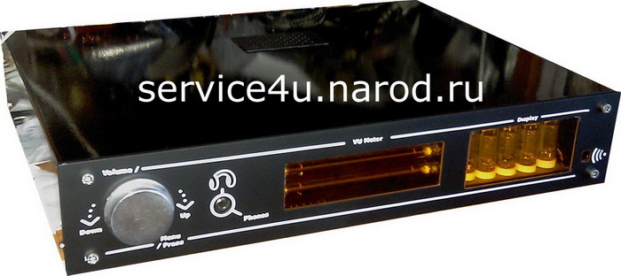
The windows in the front panel are milled. The glass is also processed with a cutter so that it is simply inserted into the window with effort. From the front, when you swipe across the panel, the height difference between the edge of the window and the beginning of the glass is almost not felt. And this is guud! The ring around the encoder is laser cut from 10mm thick plexiglass. Ring wall thickness 1mm. When landing the encoder handle inside the ring, the clearance around the circumference of the encoder handle is 0.5mm. The corrus itself is made of Aisi 304 stainless steel. The front panel is made of 5mm thick duralumin.


Tube brightness
Treble
Bass
Inputs
Rare panel
Rare panel
inside
Side view
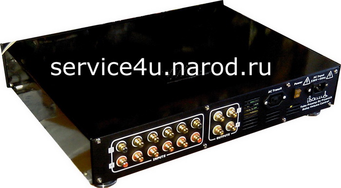
Side view
: : Final Check/All Done : :
After assembly, I download the Denon Audio Technical CD, and check the assembled device.
Happy New Year!!!
31.12.2012