microcontroller. ...and what to do with it
Today, when it's 2017, it makes no sense to talk about obsolete interfaces like LPT and COM from the pages of your site (as well as these ports are not in modern laptops. True, they still remain optional in the form of pins on motherboards from some manufacturers). If only as an archive, like, nostalgia - as it was. Today everything is very simple - I bought an AVR mkII (USB) original programmer or its clone and no fossil COM/LPT.
Today, amateur radio forums offer many options for assembling a clone of the AVR mkII programmer - these are both whales and ready-made devices at a price of no more than 10 bucks. And that's it!!! We get 3in1 - ISP / PDI / TPI interfaces.
It is enough to enter the query "AVRISP-MKII do-it-yourself" or "AVRISP-MKII clone" in the search engine and you will get many links to circuits and kits for making a clone of this programmer.
But not everyone has such an opportunity - they will buy or solder a clone. Therefore, as exhibits of the museum of old interfaces of AVR microcontrollers, I will leave information about them on this page. Just to be able to get it.
Microcontroller. ...and what to do with it
There are many resources on the web about microcontroller (MC) applications and programming. You can flash (program) the MK using a programmer. Programmers are different. In the West, there are "starter kits" that are designed to program several types of MK with buttons and LEDs (to work with interrupts). There are several types of such programmers: STK200/300/500(501/502), ICE40/50, JTAGICE, ICE200, AVRISP.
LPT Interface
This circuit is connected to the LPT port and outputs the signals necessary for normal operation with the MK:
SCK is the clock signal, MOSI is the master output-slave input, MISO is the master input-slave output, RES is the programmable MCU (MCU) reset, GND is the common ground, and Vcc is the MCU supply voltage. In the circuit, the 74NS244 microcircuit can be replaced with KR1533AP5, the 1N4148 diode with KD521, KD522. Instead of 74NS244, K555AP5 can be used. This microcircuit prevents parasitic interference in the cable and protects the LPT port. The Pony program works with this programmer. You can get it at http://www.lancos.com.
This circuit (given to understand the idea), let's call it a reference, connects to the previous one: J1 CON10 connects to J2 STRIP 1X9 - you just need to match the signals and everything will work (tested). Generally speaking, you can connect an MK with quartz and two capacitances to any of the adapters. Serve food and you can safely sew. The main thing is to know which adapter you are soldering and which specific program supports it.
There is also an Altera Byte Blaster and STK200/300 adapter. You can get the program for them here (the program supports both of these adapters, it works from the command line). I soldered the STK200/300 adapter. Here is his diagram:

Schematic diagram of the Altera Byte Blaster adapter looks like:

All adapters (programmers) presented here implement the In System Programming, ISP principle (sometimes the term In Circuit Programming, ICP is used), i.e. MK programming directly in the device: solder a connector with 6 or 10 pins on the board, route signals to it, and now if you need to program the MK, connect the cable from the programmer to this connector and after a few seconds the firmware (firmware) of the MK will be updated - without removing the MK from the working board.
There is one more adapter: SP12 also with LPT interface. An online page with a detailed description of the software installation procedure and a detailed photo description is here . I will give only a diagram and a couple of photos of what it is.

COM Interface
Everything is fine if the LPT port is free. What if you're busy? For example, I have an LCD (4x20) connected to the LPT port and the jaLCDs 3.11 program is running. Well, here are some options:
1. connect the programmer (adapter) to the USB port - this is worth a lot of work for now. Such programmers are already being sold abroad, though they cost about USD90;
2. connect the LCD to the USB-port (here things are somewhat simpler, but...);
3. Connect the programmer to the COM port. For this, after all, everything is there and the scheme (even two) and the description of the method - only the desire remains, but there will be time.
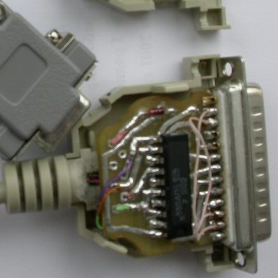
A schematic diagram of such a programmer and a description of the programming method can be found in Atmel's proprietary description "AVR910". It is built on MK AT90S1200. You can also download firmware for AT90S1200 there. I replaced the transistors in the programmer circuit with just one microcircuit - MAX202CPE. With the same success, you can replace it with MAX232, etc. with the appropriate refinement of the circuit, I think it's not difficult. This prommer works with AVRProg, which is part of AVR Studio.
COM programmer on at90s1200 looks like this:

The disadvantage of this programmer is the low speed (19200 baud). This is fixable, because. there is another diagram (on at90s2313) for the COM port. The speed of data exchange with the COM port is 115200 kbps.
In the diagram below, conclusions 7 and 8 must be swapped !!!. Conclusions 13 + 7 and 14 + 8 can not be combined. Similarly, you can not combine 12 + 9 and 10 + 11. Pins PD2 and PD4 each have one LED for reading and writing, respectively (plus). You can not put them, because. if you use the "LED" signal, then the LED connected to "LED" will signal any access to the MK - both "read" and "write". The programmer circuit looks like:
: : Firmware : :
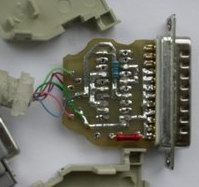
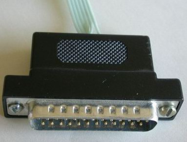
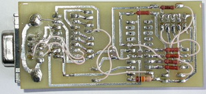
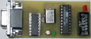
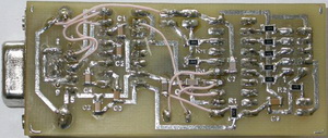
USB Interface
The printed circuit board was made using the same iron method, although the width of the tracks is 0.5 mm (this is the maximum width of the tracks on this board).
Everything is sewn by the AVRprog program included in AVRStudio. The speed, of course, is not enough - 128000, but what do you want from a COM adapter.
I use here FT232BM chip. This is a USB to virtual COM port adapter. The printed circuit board of the programmer is double-sided.