Indication "Radiotehnika MP7301" |
RU |
After connecting resistors R5, R6 adjust the signal level, resistor R16 - sensitivity. In the same way, you can connect display units from other tape recorders (Yauza, Mayak, etc.)
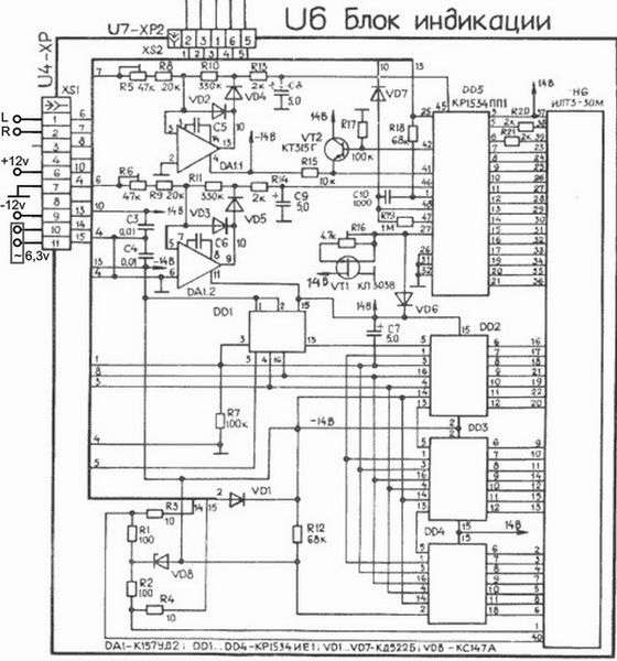
Some hams supply 5V DC instead of 6.3V AC (I tried this connection method the same way). As a result, the visibility and intensity of the illuminated segments of the indicator drops significantly, and the glow becomes fragmented along the length of the segment. The best method is to use AC6.3v filament.
More...
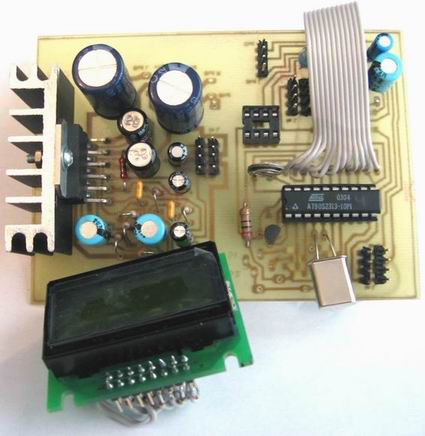
Simple tone control: TDA8425 v.1
Ruslan Avilov's device was used as a prototype.
AT90S2313;
TDA8425;
TDA2004;
SC0802DULB-XH-GB-K;
TLE4260 (Power Supervisor) replaced by MCP100-475.
Selecting the source of the input signal (Input "A", input "B");
Adjustments: loudness, bass, treble ;
Sound modes selection: stereo, mono, pseudostereo, surround.
Typical TDA2004 switching circuit in a two-channel version is used as a circuit diagram of the PA.

: : Firmware : :
Simple tone control: TDA8425 v.2
Device Features:
- selection of the input signal source (Input "A", input "B");
- adjustments: volume, bass tone, treble tone, balance;
- selection of sound modes: stereo, mono, pseudostereo, surround;
- "MUTE" mode.
AT90S2313 has been replaced by ATMega8.
On the circuit diagram of the device at the bottom left is a diagram of the PA for a piezoceramic emitter. The input of this PA should be connected to pin 24 (PC1) of the AT Mega8.


: : Firmware : :
Simple tone control: TDA7313
Two more timbral blocks are located here. It makes no sense to duplicate them on this page - just open the link, get acquainted.
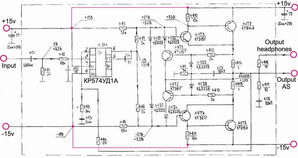
Headphone Power Amplifier
The peculiarity of the circuit is that in the original circuit, the preliminary and final stages are powered separately. The preliminary stage is powered by +/-15V, the final stage is +/-12V. I have tested this inclusion. Everything works, there are no problems. And then, I combined the power supply of the cascades together (shown in red lines in the diagram) - everything worked stably.
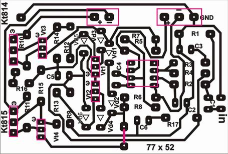
The printed circuit board is shown in the picture below. The power supplies of the cascades are separated. To combine power stages, simply connect jumpers of the same-name contacts "+" and "-" on the printed circuit board. The output of the "Output AS" scheme is not used.
You can also transfer to import - why not...
Connoisseurs of USSR audio circuitry will easily recognize the given amplifier circuit and name the brand of the original tape recorder. This is Orel. Perhaps, in other devices of the USSR times, this scheme was also used.