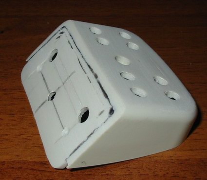
USB Light
We take the PC mouse and cut off the front (the one that is under the palm) part of the body. Then, from the remaining plastic, we cut out the back wall for the future body of the device with a dremel and glue it. For gluing, I used dichloroethane-based glue. After gluing, the lower part of the housing with the back wall is shown in the illustrations. Using a dremel, we grind the seams. After that, we give some smoothness to the back wall with fine-grained sandpaper. The machined and glued back wall is shown in the figure.
Now we need to decide on the number of LEDs to be installed. Please note that when connecting a device to a USB port, High-power bus-powered functions should not draw more than 100mA when turned on, and may draw up to 500mA when configured.
In our case, configuration is not provided and the power consumption of our device is determined only by the number of connected LEDs.
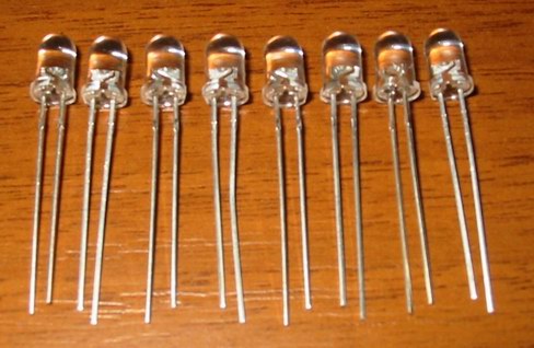
One LED consumes about 20mA current. Based on this, and estimate the total current. Because The white LEDs I bought are designed for a supply voltage of 3.7V, a brightness of 8kDl, a diameter of 5mm, and the supply voltage from the USB port is 5V, then the LEDs must be connected through a limiting resistor. On the radio market, there are LEDs of various brightness: 3kDl, 8kDl, 10kDl, which rise in price very sharply depending on the brightness, but they all have a MTBF of 90 hours (according to the seller). So think about which ones to buy.
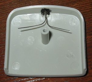
A blue LED with a nominal voltage of 5V was also glued into the top cover of the device case. You can read about how to calculate the resistance of a limiting resistor and the use of elementary electronics on the Internet.
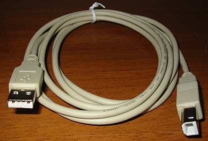
As a connecting cable, we use the “USB A to USB B” adapter, in which we cut off the “USB B” connector, shorten the “D +”, “D-” conductors, put cambric on them, and, passing through a plastic tube, solder the supply conductors into our device.
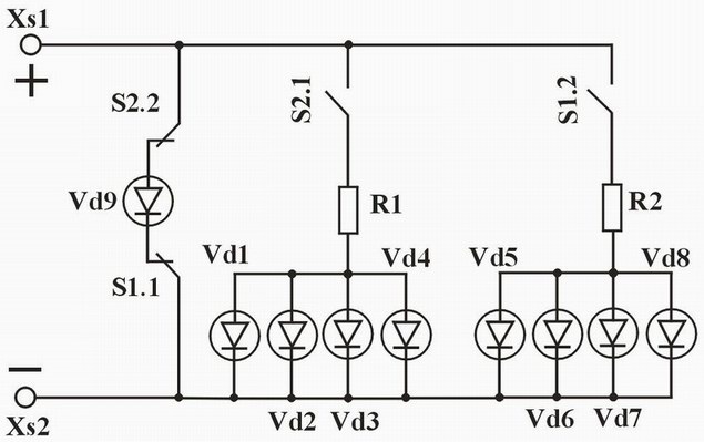
Let's also provide for some convenience when working with our "USB Light": I decided to introduce two two-position switches into the circuit, through which you can adjust the number of connected LEDs, and, as a result, the illumination of the working surface, as well as turn on / off the lamp.
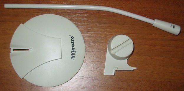
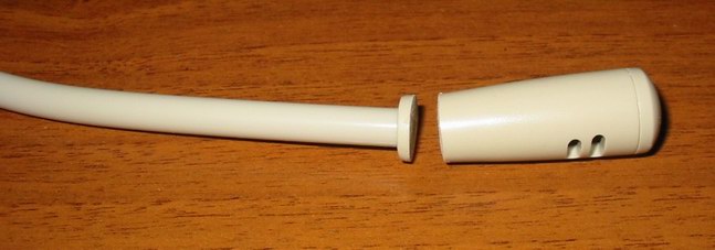
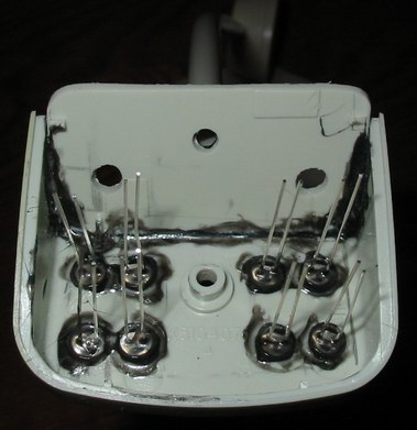
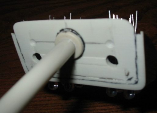
A multimedia microphone was used as a stand and holder for our lamp. The microphone with cord was removed from the plastic tube and a thickened tip was cut off with a dremel. Next, we mark the holes for the switches and the connecting cable on the rear wall of the case, for the LEDs in the lower part of the case and drill.
Glue the LEDs into the drilled holes.
We glue the plastic tube to the back wall of the lower part of the case coaxially with the hole for the cord.
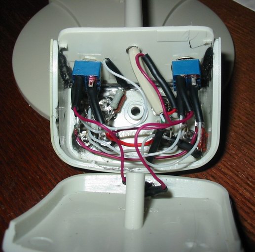
We solder the switching circuit.
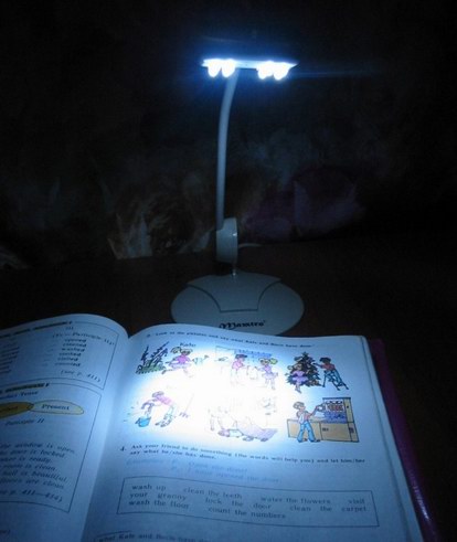
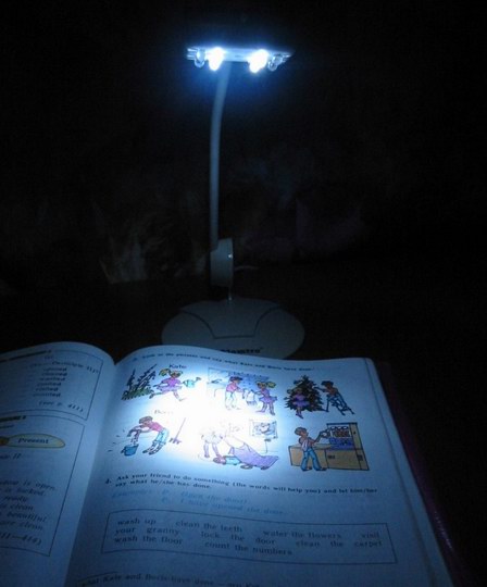
When one of the switches S1 or S2 is turned on, one four LEDs (“low beam”) lights up, and the blue LED goes out. When the second switch is turned on together with the first, another four LEDs (“high beam”) light up, the blue LED is also de-energized.
In the positions of the switches shown in the diagram, only the blue LED is lit (so that in the dark, when the computer is powered off, you can easily find our USB Light lamp).