DAC 24bit/192kHz
To significantly improve the quality of music programs played by CD-ROM drives, this design was assembled.
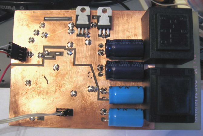
The photo shows holes in two colors (along with white) - blue and pink. Two different colors represent two different screens - analog and digital. Colored holes are soldered through jumpers on both sides of the printed circuit board. You should also carefully solder the "earths" of 4 electrolytes, standing immediately after the diode bridges. Shields must NOT be connected.
In the device in the output filter, made on an operational amplifier, you should install fixed resistors no worse than 1%. It is possible to use another operational amplifier, for example, MC33078, OPA2604, etc. The circuit capacitors on pin 8 of the CS8416 must be ceramic (1000pF - ceramic C0G or NP0, 0.022uF - X7R) and be at a minimum distance from pins 7 and 8, blocking capacitor The 1000pF on her analog power should be as close to pins 6 and 7 as possible (an example of the wiring is shown in her datasheet).
Schematic

PCB

PCB

Ground shields

Bottom

Top