IR rays and why it is needed...
Computer Management
There are dozens of resources (if not hundreds) on the web about controlling a PC from an RC remote control from household appliances and it is written in different ways and about everything. I won’t reveal anything new to you here, I just have a phone with an infrared port and I wanted to upload a few favorite tunes to my phone - this led to writing this material and creating (repeating) several devices.
1. Project by Igor Cesko
The device is made on AT90S2313-10. Works on the USB protocol. Designed to control a PC from a remote control from household appliances. To work with a PC, the Girder3.29 program is used. In my design, I used an IR receiver type TSOP 1736. All radio components are SMD (surface mount). We buy all radio components. We make a printed circuit board with a proven iron method. Read here for how to do this. We sew a microcontroller. We solder the radio components. We connect to the USB connector. We install drivers. In the control panel in the device section: Universal Serial Bus USB Controllers, after installing the drivers, a new device will appear: Infrared computer remote control IgorPlug-USB. Next, install Girder, in the settings of which we connect the plugin to work with the aforementioned device. And that's all ... Everything worked for me right away. Well, almost immediately. The fact is that despite all the previous experience with USB devices, I mixed up the power supply on the printed circuit board. After the first connection, the mouse disappeared, my LCD indicator went out, but there was no smoke or smell. About 15 seconds passed while I checked the voltage at the microcontroller pins with a tester. Device turned off. The microcontroller has failed. Soldered all other details. Made a new PCB, soldered everything back. Everything worked. Moreover, immediately and as needed.
PCB.Top
PCB.Bottom
Top

Bottom

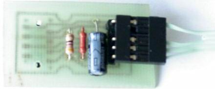
2. IrDA for mobile phone
It's easier here. We take a circuit, buy radio elements, make a printed circuit board, solder it, connect it to the motherboard, turn on the computer, set it up and everything works. The only problem is the different IrDA pinouts on motherboards from different manufacturers. Pay attention to this - your pinout may not match mine! The IrDA connector pinout is in every motherboard manual. I have EpOX MW. I tried it on another EpOX board - everything worked. The IR port worked without problems with Alcatel735, Mitsubishi phones.
pcb
Final
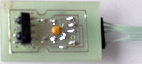
Test device
The task was to use the infrared port to connect a Samsung C100 mobile phone. There are several programs that allow you to connect to the Samsung C100 phone via IR beams: EasyGPRS 2.1.8 (27Mb) and SamsungPhoneManager 1.8 b5. There is only one problem - a virtual IrDA COM port is used, through which all this works. But there is nothing wrong here either. After you soldered this board and connected it to the MB, after turning on the computer, you need to do the following in the BIOS settings:
1. Integrated Peripherals->>SuperIO Device->>UART Mode Select->>IrDA
Well, you can also enable full duplex. The rest of the settings can be left unchanged.
2. In the file: C:\WINNT\inf\msports.inf it is necessary in the section
[Std]
% *PNP0400. DeviceDesc % = LptPort, *PNP0400; Printer Port
% *PNP0401. DeviceDesc % = EcpPort, *PNP0401; ECP Printer Port
% *PNP0500. DeviceDesc % = ComPort, *PNP0500; Communications Port
% *PNP0501. DeviceDesc % = ComPort, *PNP0501; Communications Port
;
; Add another line
% *PNP0510. DeviceDesc % = ComPort, *PNP0510; Generic IR device / COM-порт
in section
[strings]
MS = "Microsoft"
Std = "(Standard port types)"
PortsClassName = "Ports (COM & LPT)"
*PNP0400. DeviceDesc = "Printer Port"
*PNP0401. DeviceDesc = "ECP Printer Port"
*PNP0500. DeviceDesc = "Communication Port"
*PNP0501. DeviceDesc = "Communication Port"
; Add device description for PNP0510
*PNP0510. DeviceDesc = "Generic IR device / COM port"
In the list of devices, IR Devices should appear at the very bottom, and in it - Built-in IR Device. After that, you can work with this device as with a regular port. Download the virtual_IrCOMM2k-eng.rar file from the network and install the virtual IR port. After installation, in the COM and LPT ports section, you should see Virtual IR COM port.
Install one or both programs (both programs work for me: EasyGPRS and SamsungPhoneManager). In the settings, select IrDA (for EasyGPRS) or COM4 (for SamsungPhoneManager). The COM port number is a purely personal matter. Usually there are one or two of them per MV. Simply, they may or may not be busy with you. In general, the closest port after the built-in MB COM port is assigned as virtual. In EasyGPRS, virtual COM is immediately associated with IrDA and is designated as IrDA in the list. And when you select the IR port in the settings, there will be something like: COM1, COM2, COM3, IrDA ... There will be something in SamsungPhoneManager: COM1, COM2, COM3, COM4 ... After that, activate it in the non-settings IrDA phone and lay down next to the transceiver. After that, an IR icon appears in the system tray (below, near the clock), and when you hover over it with the mouse, a tooltip appears: "SamsungSGH-C100 is within visibility range." We launch one of the programs, click "Connect" or "Reconnect" (depending on the program) and everything is OK.
3. IrDA with different interfaces
You can repeat other people's devices as much as you like. It's time to show something.
Because both programs for Samsung SGH-C100 work through a virtual COM port, then my scheme will work the same way - through a virtual COM port.
The basis of the circuit is FT232BM, a microcircuit that implements a virtual COM port. The most complete information, along with typical wiring diagrams, can be found on manufacturer's website. On the same chip I built ISP - USB programmer for AVR. The schematic diagram looks like:
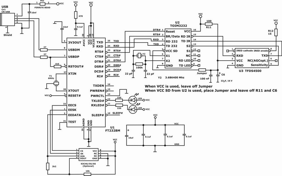
Chip 93C46 / 56/66 - installed "optional". If you do not connect two or more FT2XX devices to the computer SIMULTANEOUSLY, then 93С46/56/66 can be omitted. For 93С46/56/66, two options for internal organization are possible: 8 bits or 16 bits. This is selected by connecting pin 6 to "+5V" or to a common wire. In our case, it is necessary to put pin 6 on "+ 5V" (16-bit organization will be selected). I left pin 7 unconnected. When choosing a 93CXX chip, be careful: different manufacturers have different pinouts (rotated by 90 degrees). In addition, for the same manufacturer, the pinout varies depending on the case. I used 93C46 from ATMEL. In 93C, Manufacturer, Manufacturer ID, Vendor ID, Product ID, Description are sewn up so that when more than one device is connected at the same time, they do not conflict with each other, and the computer knows which device is doing what. It's all simple (despite the number of fields). After reading the documentation, everything becomes completely clear.
It remains only to solder this circuit and check it on a breadboard.
You can chat with FTDI engineers - they answer quickly and to the point. You can even ask them for unique PID's for your device - to be unique.
Moving on...
Why am I writing all this? It's just that recently on forums dedicated to mobile phones, almost EVERYWHERE and EVERYWHERE they write, they say, "... there are no schemes for IR ports, but I don't want to buy a ready-made device." If you don't want to, then you are here. But if you don’t know how to hold a soldering iron in your hands, it’s better to buy a ready-made device - save money and nerves. Here are a few more schemes that are completely easy to figure out after spending half an hour on the network - an hour. I’ll say right away that I didn’t find any of the microcircuits (except for the TFDS4500/4100) on the radio market either, and no one wants to take it to order, and, therefore, there’s no way to experiment with them yet. So, the solution to the problem "into" is the classic scheme of 2003 from Sigmatel:

Another classic schematic from the end of 2004 from Sigmatel:
Not enough??? Then another solution from Hewlett Packard - having a TTL level signal at the input, we get another implementation of the IR port:
And where do you get the TTL logic level signal from? We connect FT232BM, and we get USB at the input and TTL-level COM port signals at its output. The circuit diagram looks like:

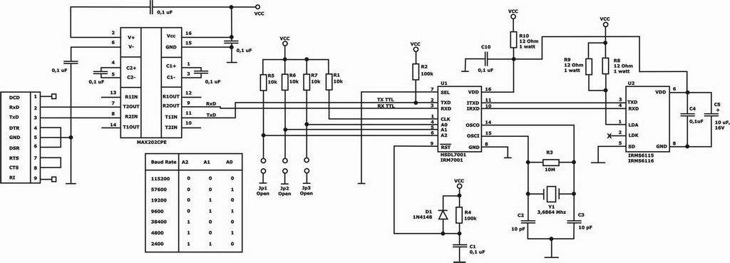
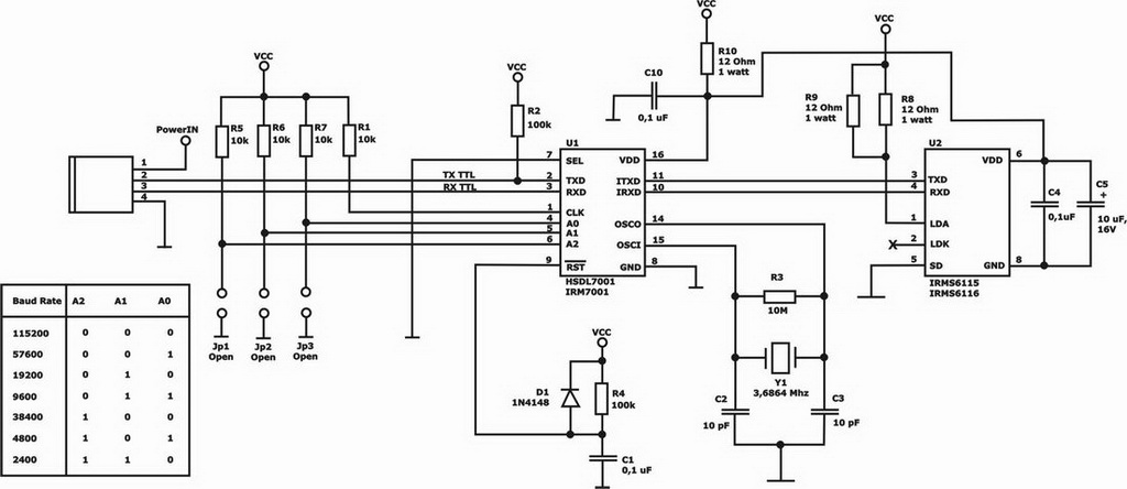
You can also draw a diagram of the IR port like this: from the COM port, we send a signal to the MAX202CPE. From the output of the MAX202CPE, the signal (and at the output of the MAX202CPE the signal is already TTL) is fed to the HSDL7001 / IRM7001 (the circuit was given above) and that's it! Do not need anything else. Here is another IR port for you: