50GDN Subwoofer /Part 1/ |
RU |
Currently, the World Wide Web contains a huge number of various descriptions and manuals for the manufacture of subwoofers of various design and technical characteristics. After reviewing several similar descriptions, the author chose the Bandpass 6a model using the head of the former domestic manufacturer Radiotekhnika 50GDN. The author did not use a lower power head. The 35GDN has a somewhat small diffuser diameter. And this is an argument! So, either 50GDN or 75GDN. In terms of their parameters, both heads are almost identical, but 50GDN is cheaper. The author did not consider imported dynamic heads as a subwoofer head - I did not want to buy a “Chinese pig in a poke”. Serious dynamic heads are imported and are not cheap. Another thing is the dynamic heads produced by the former USSR. On each of the dynamic heads there is a quality mark - this is at least something, but it means (perhaps this is just a convention). Yes, and technical specifications can be found on the global web. But the fact is that these dynamic heads were produced by a number of factories, and as a result, the characteristics of one dynamic head can vary greatly depending on the manufacturer and, as a result, differ from the technical characteristics found on the Internet and dynamic head guides.
First, let's choose the acoustic design of the dynamic head. There are several common types of acoustic design for dynamic drivers.
1 - closed box (Closed). In this case, we get the lowest efficiency of the speaker system and the need to supply a fairly high power, as a result of which the dynamic head is likely to fail. With such a design of acoustic design, the fastening of the walls of the case should be the most durable, because. a high pressure is created inside the box due to the movement of the diffuser, which will try to compress the elastic air in the closed volume.
2 - phase inverter (hereinafter referred to as FI) (Vented). The model is somewhat better in terms of performance. The distortion introduced by the speaker is minimal. The FI itself increases the efficiency of the dynamic head. All difficulties begin when calculating FI. The fact is that a large diameter of the FI requires a large length, and a small one just a small one. It would seem that everything is fine. Do not rush to rejoice. Moving, the head diffuser moves elastic air through the FI tunnel. The volume of air in the tunnel is constant, which means that the speed of air movement through the tunnel FI will be as many times greater than the oscillatory velocity of the diffuser, as many times the cross-sectional area of the tunnel is less than the area of the diffuser. Because of this, air turbulence will begin in the FI tunnel and the FI will begin to whistle. So it turns out that in calculations, as a rule, the length of the FI tunnel turns out to be excessively large, but this can be circumvented
3 - bandpass (hereinafter referred to as BP) (Bandpass). The dynamic head is enclosed between two volumes of air. It is adjusted over a wide range by selecting the volumes of the front and rear chambers and the tuning frequency of the two FIs. The efficiency is the highest of all discussed above. There is only one drawback - the PSU is the most difficult to manufacture. Although, I would not call it a disadvantage, it is rather a virtue.
There are a number of specialized programs for calculating box parameters: JBL SpeakerShop, Box Plot, Blaupunkt BlauBox. The author used the winisdbeta program, as it left the best impressions when working with it. When modeling the structure, it is easy to make sure that the FI loses to the BP with the same (small) volume of the box. But with a large volume - on the contrary, the BP will lose. But given that most of us live in average apartments and drive average cars, large volume is not our method. On the other hand, you should not get involved in its reduction - it will not get better. Therefore, a compromise will have to be found. You can also see this when modeling your subwoofer in the winisdbeta program - vary the volume parameters of both BP cameras, tuning frequencies and FI length and you will immediately see how this affects the frequency response of your future brainchild.
In order to design and manufacture a subwoofer cabinet, it is necessary to know some characteristics of a driver. Required parameters for calculation:
Fs — resonance frequency in open space, Hz; Qts — full quality factor of the dynamic head; Qms — mechanical quality factor; Qes — electrical quality factor; Vas — equivalent volume, l; Sd — the effective radiating surface of the diffuser, m2. |
||||||
| We will measure the parameters of the dynamic head according to the method described in [5]. We assemble the circuit according to Fig.1. |
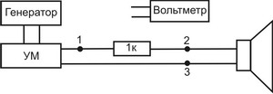
Fig. 1.
Instead of a generator, it is convenient to use the output of a computer sound card and, using the appropriate software, generate sinusoidal signals with a frequency of 0-200 Hz. A 1kΩ resistor stabilizes the current through the speaker. The author used a 7.5W resistor.
We measure the resistance of the dynamic head with an ohmmeter. This will be the desired Re - resistance to direct current.
We place the dynamic head away from the walls, floor and ceiling (ideally, we hang it). We connect a voltmeter to the PA output (Fig. 1, points 1 and 3) and set the output voltage from 10V to 20V at a frequency of up to 200Hz. To find the resonant frequency (Fs) of the dynamic head, we connect a voltmeter to the dynamic head (Fig. 1., points 2 and 3), smoothly change the generator frequency and look at the voltmeter readings. On a sheet of paper we write down the set frequency of the generator and the readings of the voltmeter. The frequency at which the voltage on the voltmeter will be maximum (a further change in frequency will lead to a voltage drop) will be the main resonance frequency for this dynamic head. When measuring Fs, the author changed the frequency with an interval of 1 Hz. We get the graphical dependence U=f(F), shown in fig. 2.
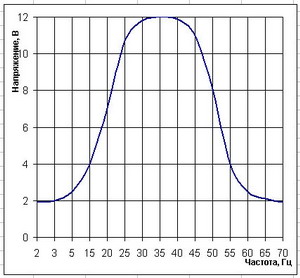
Fig. 2.
When measuring Fs, we have the minimum voltage Um and the corresponding frequency F1, located in the frequency range up to Fs, and the frequency F2 at the same voltage value, located behind the frequency Fs. The frequencies F1 and F2 correspond to the voltage U12, which is approximately equal to 0.707Us. Also, we have the voltage value Us at the frequency value Fs. We need these data to calculate U12, Qms, Qes and Qts.
As can be seen from Fig. 2, for this dynamic head 50GDN-3-4, the frequency of the main resonance in open space is 35 Hz. F1 = 16 Hz, F2 = 54 Hz, Um = 1.9 V, Us = 12 V.
We make the necessary calculations using the formulas:
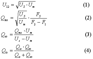
| The results of all our measurements give: Qts = 0.37 |
||||||
Sd – is the effective radiating surface of the diffuser. It coincides with the constructive one and is equal to: |
![]()
where R is half the distance from the middle of the width of the rubber suspension on one side to the middle of the rubber suspension on the opposite side. Half the width of the rubber suspension is also a radiating surface. The unit of measure for this area is square meters, and in the winisdbeta Sd program it is necessary to substitute in square meters.
Vas is taken equal to 90l.
After substituting all the parameters in the winisdbeta program, we have the following:
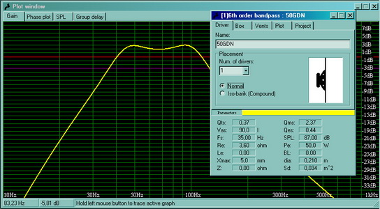
Fig. 3.
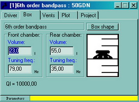
Fig. 4.
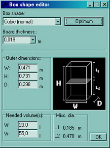
Fig. 5.
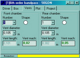
Fig. 6.
The wall thickness is chosen equal to 19mm, the material is imported chipboard. As connecting elements - a wooden bar 40x40mm. The author did not use the end surfaces of chipboard (even if imported) - they are too loose, in addition, chipboard can delaminate. It should be noted here that the beam, with which the walls of the subwoofer case are attached to each other, also occupies a certain volume.
And if this volume is not taken into account when modeling the case, then the result is slightly different volumes of both cameras and, while maintaining the frequencies of the PHI settings, their length and diameter, the frequency response of the finished product will change very much and not for the better side. But even here you can get out[4] regarding the length of the FI. Ultimately, it will be possible to simply replace both FIs, taking into account changes in chamber volumes. On fig. 3 - fig. 6 shows the structural characteristics of the subwoofer without taking into account the volume of wooden beams. In other words, this is what we want to get.
Taking into account the volume of wooden beams in both chambers, we have: the volume of the anterior chamber will decrease by 2.4 liters, the rear chamber - by 6.5 liters. Those. As a result, we get what is shown in Fig. 7, 8.
To maintain a smooth frequency response, the settings of both FIs have been changed, and, as a result, their length has changed.
Finally: we make a subwoofer case with external dimensions according to fig. 5, but in reality our product will have the characteristics according to Fig. 7, 8without taking into account the installation of the filler.
A few words about the length of FI. In the anterior chamber, the FI length is 95 mm (Fig. 8). This is more than normal and acceptable. We add 2-3 cm to its length (you still have to adjust) and make it. But for the rear camera, the length of the FI is somewhat too big. It can be shortened. How to do this - the calculation procedure is described in the web. I will give only the main points.
The formula for calculating the shortened version of the FI is:
![]()
FI tuning frequency Fb - in hertz, chamber volume V - in liters, length L and diameter D FI - in millimeters.
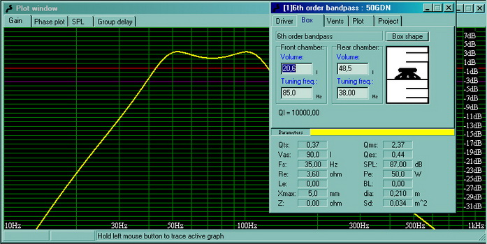
Fig. 7.
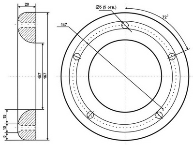
The “-0.85D” correction appears due to the fact that one end of the FI is in the plane of the wall and there is a virtual extension of the FI, as a result of which its tuning frequency changes and the frequency response of the subwoofer will have a “failure ". In the winisdbeta program, this amendment has already been taken into account. Based on this, if we install a flange on the second end of the FI, which is located inside the chamber in free space (Fig. 9), we will get a FI with an even shorter length while maintaining the diameter and tuning frequency. And then the formula for calculating the length of the FI will take the form:
![]()
It is easy to see how our 287 mm (Fig. 8) at 38Hz (37.7Hz according to formula (6)) turn into 192 mm (according to formula (7)) with a flange on the second end of the FI at a tuning frequency of 38Hz of the rear camera. This is our method - a normal short PHI. We leave this option. The flange is made of organic glass 4 mm thick (Photo 4).
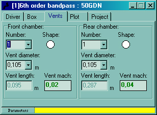
Fig. 8.
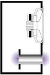
Fig. 9.
After all the walls are cut out, we proceed to attaching the surfaces to each other.
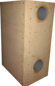
On fig. 10 shows the overall design of the subwoofer cabinet.
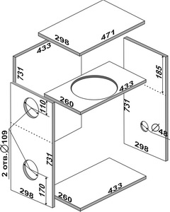
Fig. 10.
50GDN subwoofer/Part 2/
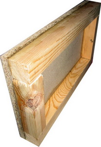
All joints are made on wooden bars. Before attaching the beam to the walls of the subwoofer housing, the beam is pressed against the wall from below and recesses are drilled through the wall into the beam with a drill with a diameter 2 times smaller than the diameter of the self-tapping screw, with which the beam will subsequently be screwed, with an interval of 5 ... 7 cm along the perimeter of the surface with an appropriate indent from the edge of the wall surface. The amount of indent depends on the parameters of the wooden block used in the design of the subwoofer cabinet and the diameter of the screw. On the surface of the wall, all holes are countersinked.
Before screwing, the surface of the beam to be screwed is thickly smeared with undiluted PVA glue. Glue do not regret. In the process of screwing the beam to the surface of the subwoofer housing wall, excess glue is squeezed out of the joint and removed manually.
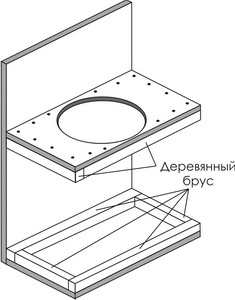
The bottom is prepared first. On the one hand, a wooden bar around the perimeter is attached to the surface of the bottom of the subwoofer case cut to size.
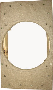
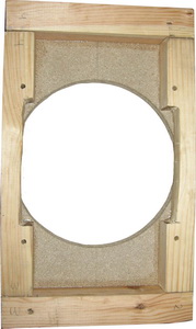
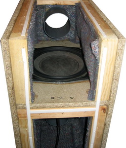
In a shelf cut to size for a dynamic head, a hole of the appropriate size is cut out for a specific dynamic head, holes are marked and drilled for fastening the dynamic head. Next, a wooden bar is attached around the perimeter.
Then, we attach the bottom to one of the side walls of the subwoofer case and, having carefully measured the distance of 185 mm from the opposite edge of the same wall, we attach the shelf for the dynamic head. We also attach the second side wall of the subwoofer case to the bottom and shelf for the dynamic head.
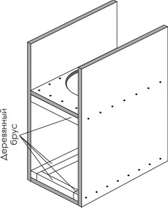
After that, we fasten the beam around the perimeter of the front and rear chambers. Because there is already a beam on the bottom and on the shelf for the dynamic head, then for the rear chamber it is necessary to fix the beam only along the vertical borders of the chamber on both sides. And for the anterior chamber - along the vertical borders on both sides and two horizontal ones.
We also attach the second side wall of the subwoofer case to the bottom and shelf for the dynamic head.
After that, we fasten the beam around the perimeter of the front and rear chambers. Because there is already a beam on the bottom and on the shelf for the dynamic head, then for the rear chamber it is necessary to fix the beam only along the vertical borders of the chamber on both sides. And for the anterior chamber - along the vertical borders on both sides and two horizontal ones.
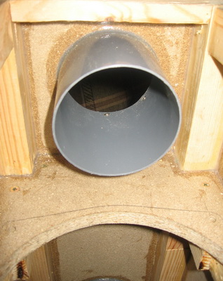
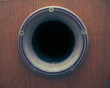
Further, in the front wall of the subwoofer case cut to size, we cut out two holes with a diameter of 109 mm for phase inverters. It is 109mm that makes up the outer diameter of a sewer plastic pipe with an inner diameter of 105mm. We prepare phase inverters in advance, because. their dimensions become known to us after modeling the subwoofer in the program and choosing the final version of the tuning frequency of each phase inverter, as well as their other parameters: the diameter of the phase inverter and the volume of the chambers.
If subsequently the adjustment of the phase inverters is not planned, then the surface of the cut out holes for the phase inverters is thoroughly coated with PVA glue. We do not regret glue - the excess will squeeze out anyway. We insert the phase inverter and fasten it with 6 self-tapping screws from the inside of the phase inverter. We do the same with the second phase inverter.
If you plan to adjust phase inverters (very desirable, almost mandatory), then silicone sealant will work well instead of glue. And it is better to cut the phase inverters a little longer, with a margin.
When the front wall with phase inverters is ready, it is screwed to the end surfaces smeared with glue of our design.
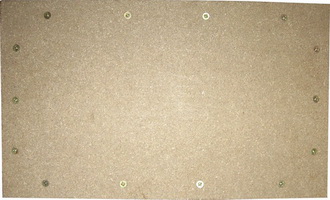
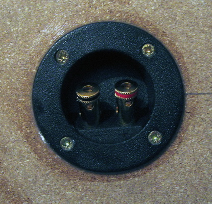
We drill holes for self-tapping screws in the back wall. Cut out a hole for contacts of the appropriate size. We apply silicone sealant to the contact panel around the perimeter. Using self-tapping screws, we fasten it into the hole in the rear wall.
We drill holes for attaching the cover.
We do not put the lid and the back wall on the glue - we will have to remove them more than once. With a vacuum cleaner, we cleanly remove sawdust and small chips from the inside of our structure.
After that, carefully seal all seams and joints with silicone sealant. Lubricate them carefully. Do not forget the mounting holes for the FI - from the inside of each chamber and from the outside. Let the sealant harden.
Now we attach the dynamic head to the holes in the shelf, specially designed for this. We first apply silicone sealant around the perimeter of the circle and let it harden just a little to create a small shock absorber. After that, install the dynamic head and tighten the bolts with force. We coat the joints of the dynamic head with the shelf with silicone sealant.
It's almost done - solder the electrical wires from the speaker head to the contact panel mounted on the rear wall. We temporarily fasten the back wall and the cover through adhesive tape for window insulation, we attract with several self-tapping screws around the perimeter for testing. We connect to the PA with a low-pass filter and listen - what happened.
There is no sound-absorbing material inside. Therefore, the sound is like this - the bass is heard - no doubt, but it is not felt by the whole body, as we would like. We install sound-absorbing material inside both chambers.
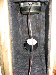
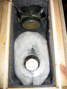
Batting and cotton wool, which is located between the inner surface of the subwoofer housing wall and the batting, were used as sound-absorbing material. What does the installation of sound-absorbing material give? On the one hand, we kill standing waves. On the other hand, we add an additional small volume to the volume of our cameras. How much sound absorber you need to install inside your product is described in the article. The inner surfaces of the cover and the rear wall of the subwoofer cabinet are also equipped with a sound absorber.
Now we connect and ... enjoy.
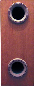
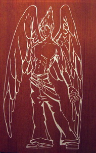
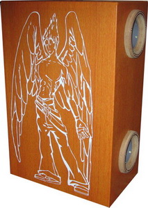
Aesthetic design depends on personal taste. In the author's performance, all the recesses of the self-tapping screws on the outside and the joints of the walls are filled with putty on wood. After the putty has dried, the subwoofer case is sanded with sandpaper and pasted over with a decorative film with a “wood-like” texture. On one of the side surfaces there is a drawing made by plotter cutting. In front, flanges made of textolite are installed on the phase inverters.
The finished device looks like:

10s order low-pass Bessel filter
When using a subwoofer as a low-frequency link for home or car acoustics, a low-pass filter is required. The low-pass filter is designed to exclude from the sound reproducing path a signal with a frequency higher than the cutoff frequency of the low-pass filter. The cutoff frequency of the filter is chosen equal to 100 Hz with the possibility of changing it. The variable cutoff frequency of the low-pass filter is chosen as such based on the dual use of the subwoofer - car and room. For a car, the optimum cutoff frequency is 80Hz. For home use, the cutoff frequency may be higher than 100Hz, but this is a matter of taste. This difference is due to the difference in the acoustic characteristics of the sound transmission (transfer function) of the car interior and the room.
There are several types of low-pass filters named after mathematicians (Butterworth, Chebyshev, Linkwitz, Cauer, Bessel) who were the first to implement a mathematical model of a particular function, through which, in turn, the transfer characteristic of a low-pass filter is expressed. The function is determined by the order of the polynomial (the maximum exponent) and the coefficients ai and bi.
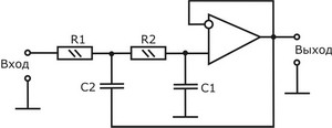
Fig. 12.
On fig. Figure 12 shows a second-order active low-pass filter with a gain of 1.
In the general case, the filter is calculated as follows. Select the cutoff frequency of the filter. Let the cutoff frequency be 60Hz. Next, choose the type of approximation. Let's apply the Butterworth approximation. Select the filter order - 2nd. We calculate the values of the radio elements included in the circuit diagram of the low-pass filter (Fig. 12). The resistance and capacitance values are obtained from the transfer function of the low-pass filter. It should be noted that with this calculation of the filter, the resistance values should be no worse than 5% for a low-pass filter up to the 4th order and 1% (or better than 0.5%) for low-pass filters from the 4th to 10th order. The tolerance of the nominal values of the capacities is 10%. Therefore, when calculating the filter, it is better to set the capacitance values and calculate the resistance values. Let C1 and C2 be given. Then the resistance values will be equal to:
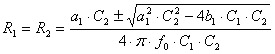 (8), где
a1, b1 - polynomial coefficients;
f0 - filter cutoff frequency, Hz;
R1, R2 - resistances of resistors, Ohm;
C1, C2 - capacitances of capacitors, F.
For the resistances of resistors R1, R2 to be valid, the following condition must be met:
![]() (9)
(9)
C1/C2 should not be chosen much larger than the right side of inequality (9).
In a similar way, a low-pass filter up to the 10th order is calculated by substituting the coefficients ai, bi of the corresponding link number into formula (8). For odd-order filters, the first-order link is placed first, the remaining links are of even order. For a link of an odd order, the coefficient bi=0. However, it should be understood that by connecting two second order Butterworth filters with the same cutoff frequency f0 in a row, we will not get a 4th order Butterworth filter with a cutoff frequency f0. We will get a low-pass filter with a cutoff frequency different from and with a different frequency response and transfer function than Butterworth. This will be a low pass filter with critical attenuation.
The method for calculating low-pass filters up to the 5th order is given in the web. You can also find low-pass filter coefficients for calculation there.
In the literature we can find a table of coefficient values for low-pass filters of various types up to 10th order and the cutoff frequency of the filter sections. Calculation of the low-pass filter by formula (8) in Microsoft Excel is quite simple. After the calculations, we obtain the resistance values of the filter links for the given capacitance values. The tolerance of the resistors must be at least 1%. There are several options here: compiling a given resistance from several resistors or using precision resistances. When calculating the low-pass filter using formula (8), it is impossible to include the tolerance of resistance values into the calculation. As a result, it will be necessary, as a result, to configure each link separately. This is acceptable for a low-pass filter of low order (up to 4th). When the order of the low-pass filter is higher than the 4th, having done the procedure for setting each link separately, you will no longer want to repeat a similar process, I assure you.
What is the order of the low-pass filter to collect?
1. The tolerance of resistances with a filter order of no higher than the 4th should be no worse than 5%. A second-order low-pass filter can also be assembled at 10% resistances. But above the 4th order - the tolerance should be no worse than 1%.
2. For clarity, let's look at the frequency response of various types of low-pass filters and different orders.
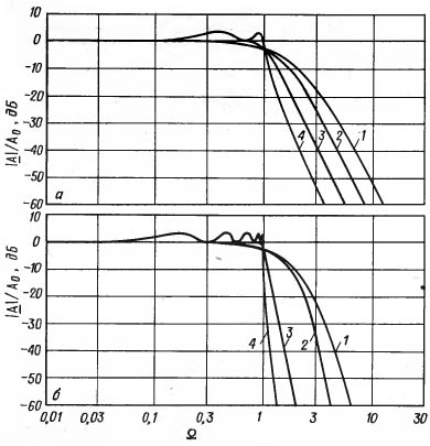
Fig. 13. The frequency response of filters of the 4th (a) and 10th (b) orders.
1 – filter with critical attenuation;
2 - Bessel filter;
3 - Butterworth filter;
4 - Chebyshev filter with 3dB non-uniformity.
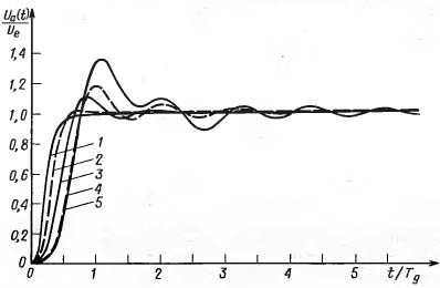
Fig. 14. Transient response of 4th order low-pass filters with stepped input signal.
1 - filter with critical attenuation;2 - Bessel filter;
3 - Butterworth filter;
4 - Chebyshev filter with unevenness 0.5dB;
5 - Chebyshev filter with 3dB non-uniformity.
The Chebyshev filter disappears immediately - without even looking at the fact that its slope is higher than that of the Bessel and Butterworth filters (Fig. 13, curve 4). We see ripple in the bandwidth. This unevenness can range from 0.5 dB to 3 dB. The sharper the rolloff behind the cutoff frequency, the higher the passband ripple. With a pulse action on the filter, very high fluctuations of the transient process (Fig. 14, curves 4, 5).
The optimal transient response is observed in the low-pass Bessel filter. This is due to the fact that the phase shift of the Bessel filter output signal is proportional to the frequency of the input signal. The Bessel filter transient has almost no oscillation. Increasing the order of this filter, starting from the 4th, leads to attenuation of the transient.
To complete the picture, let's take a look at the frequency response of the group delay and the phase shift of the 4th order low-pass filters.
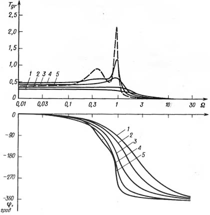
Fig. 15. Frequency response of group delay and phase shift of 4th order low-pass filters.
1 – critical attenuation filter;
2 - Bessel filter;
3 - Butterworth filter;
4 - Chebyshev filter with unevenness 0.5dB;
5 - Chebyshev filter with 3dB non-uniformity.
The maximum delay time is inherent in Chebyshev and Butterworth filters. Minimum - critical attenuation filter and Bessel filter.
In addition to the low-pass filter, we need a phase regulator - a first-order phase filter - to match the subwoofer with front speakers. In general, the circuit diagram of the first-order phase filter is as follows:
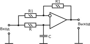
Fig. 16. First-order phase filter.
![]() (10), where
(10), where
a1 - phase filter factor Fig. 17.
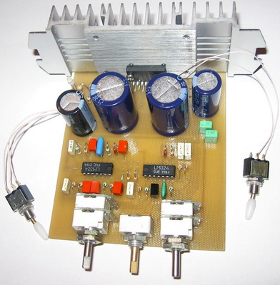
As an op amp, LM324 imported op amps were chosen. They have many advantages: 4 op-amps in one DIP14 package. The outputs of each op-amp are located at the corners of the case (pin 1, 7, 8, 14). Two- and one-polar power supply, which is important when using a low-pass filter in a car. Wide range of supply voltages. Small current consumption. The most important thing is that in the range up to 500 Hz, the quality of the op-amp is more than sufficient. Fig. 18.
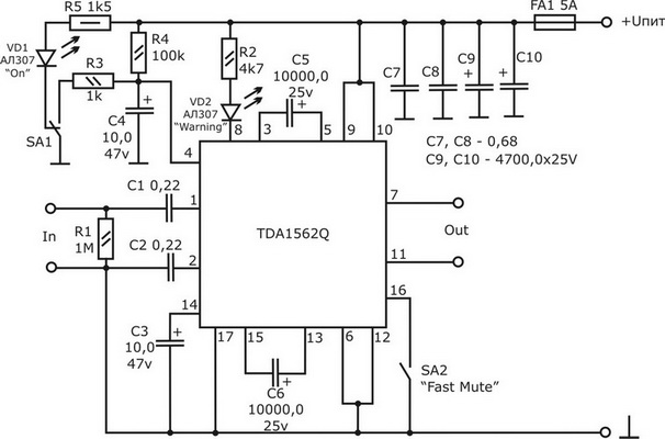
Fig. 19. Low-frequency power amplifier on a TDA1562Q chip
Switch SA1 is designed to turn the PA on and off, SA2 - to turn on the "MUTE" mode. Any small switch can be used as SA1. Fig. 18.
Fig. 19. Low-frequency power amplifier on a TDA1562Q chip
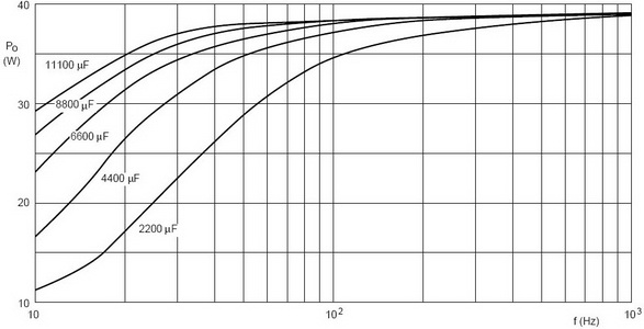
Elements SA1, SA2, VD1 and VD2 are brought to the front panel of the low-pass filter and are connected to the printed circuit board via a mounting wire. Capacitances of 10,000 microfarads each were used as electrolytic capacitors of the voltage boost (C5, C6), and capacitances of 4700 microfarads (C9, C10) were installed for power supply. This allows you to develop more power, all other things being equal. As you know, when the car engine is off, the voltage of the on-board network is 12V. When the engine is running, the voltage rises slightly, up to 14.5V, which provides an increase in the output power of the PA. For the previous modification - TDA1560Q - in the datasheet there is a dependence shown in fig. twenty.
Fig. 20. Dependence of the TDA1560Q output power on frequency at a harmonic distortion factor of 10% for various values of the electrolytic capacitances of the voltage boost
In our case, for the TDA1562Q chip, the dependence shown in Fig. 20 will differ slightly. You just need to mentally substitute the value “70” instead of the number “40” - according to the manufacturer, this is the maximum output power that the TDA1562Q provides at a supply voltage of 14.4V and a load resistance of 4 ohms, and proportionally replace the intermediate values along the Po (W) axis.
Switch SA1 is designed to turn the PA on and off, SA2 - to turn on the "MUTE" mode. Any small switch can be used as SA1.
f0 - cutoff frequency of the phase filter, Hz.
By changing the resistance R, we can set any amount of phase shift from 0° to -180° without changing the amplitude of the output signal. In this case, the phase filter is converted into a phase shifter.
In addition to the method of calculating the low-pass filter using formulas (8) and (9), described above, there are several more methods. There is also a specialized program for creating low-pass filters - FilterPro. The manufacturer of the software product is Texas Instruments. We will not stop at the work of the program itself, the program interface is intuitive. The advantage of this software product is that we can specify the tolerance of the applied resistances and capacitances. And then there is no need to select resistors.
We will not trade on the rigidity of the mentality of Western manufacturers of low-pass filters, and we will assemble a 10-order Bessel low-pass filter according to the Salena-Key link circuit with a cutoff frequency of 100 Hz, with a phase shifter and an active volume control.
On fig. 17 shows a circuit diagram of a low-pass Bessel filter of the 10th order with a cutoff frequency of 100 Hz.
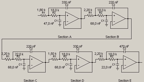
To the circuit diagram of the low-pass filter generated by the FilterPro program, we add the simplest adder on two resistors at the input. In the low-pass filter circuit, in the last link, we add a dual variable resistor to adjust the low-pass filter cutoff frequency. At the filter output we put our phase shifter and an active volume control. Finally, the circuit diagram has the form shown in fig. eighteen.

As an op amp, LM324 imported op amps were chosen. They have many advantages: 4 op-amps in one DIP14 package. The outputs of each op-amp are located at the corners of the case (pin 1, 7, 8, 14). Two- and one-polar power supply, which is important when using a low-pass filter in a car. Wide range of supply voltages. Small current consumption. The most important thing is that in the range up to 500 Hz, the quality of the op-amp is more than sufficient.
To the circuit diagram of the low-pass filter generated by the FilterPro program, we add the simplest adder on two resistors at the input. In the low-pass filter circuit, in the last link, we add a dual variable resistor to adjust the low-pass filter cutoff frequency. At the filter output we put our phase shifter and an active volume control. Finally, the circuit diagram has the form shown in fig. eighteen.
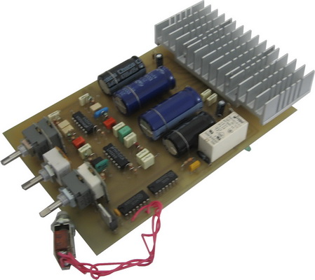
Most of the elements of the low-pass filter and PA are mounted on a printed circuit board. At one time, I made a couple of different options, incl. "slim" version.