35GDN-1-8 Sub + LP Filter |
RU |
You can read about how to remove the Thiel-Smol parameters at home here. Everything is described in great detail there, repeat here I will not repeat the same, just give the results of calculations of the main parameters of Thiel-Smol.
Thiel-Smol parameters taken from the speaker:
Qts = 0.343;
Fs = 33,2Hz;
Qms = 1.88;
Qes = 0.42;
Pe = 35W;
Vas = 40l
What do we see? The resonance frequency is 33.2Hz - this speaker needs a subwoofer!!! Now we check the ratio Fs/Qts. 33.2/0.343=96.79. Close to 100. This means that such a speaker will work better in a bass reflex or bandpass enclosure. If this ratio were about 50 or less - then only a case of the closed box type. If this ratio is between 50 and 100 - then you need to look at other parameters of the speaker - what type of acoustic design the speaker "gravitates" to. This can be done using special computer programs.


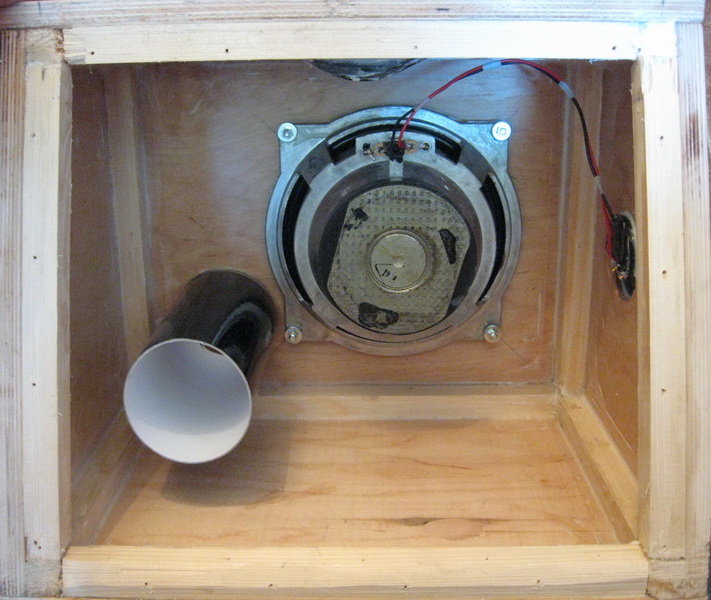


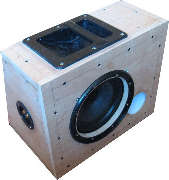

All connections are made through a bar 20x20mm. Wall thickness - 15 mm, made of plywood. Before joining, the bar on the sides adjacent to the walls is smeared with wood glue. Next, wood screws are screwed in to strengthen the connection. After the glue has completely dried, all joints inside the case are coated with silicone for tightness. Also, all the tie-in points of external components are sealed with silicone sealant - carrying handles, cups with contacts, the place where the phase inverter is attached. A decorative grille is installed on the front wall. The lower wall is made somewhat longer, so that you can safely cut off the excess from it with a hacksaw at an angle. The design of the subwoofer is specially made with an inclined rear wall - operation is supposed to be in the trunk of a car.
The filler is ordinary cotton wool, bought at a pharmacy and enclosed in a gauze bag. Along the perimeter of the rear wall, the joints are glued with insulating foam to give tightness and the ability to painlessly disassemble the subwoofer, followed by trouble-free screwing of the back wall to its original place.
Low Pass Filter


The signal from the linear output of the car radio is connected to a mixer made on DA1.1, 1.2. Further, the low-pass filter itself, Butterworth, 2nd order, with a variable cutoff frequency. The cutoff frequency of the LPF is 150Hz, which can be changed from 30Hz to 250Hz. Made on DA1.3. Further, the phase shifter, made according to the classical scheme of the first order phase filter on DA1.4. The volume controller is made electronic, on the DA2 chip - KA2250. It just caught my eye somehow, so I decided to stick it here. There is one small advantage in using this chip. The lower limit of the passed frequencies of the KA2250 microcircuit is about 20 Hz, which gives us the opportunity to refuse to use a subsonic to suppress infra-low frequencies. Additionally, on the printed circuit board of the filter there is an electronic on/off unit for the subwoofer. The on-off block is made on DD1 K155TM2, which controls the operation of relay K1, the contacts of which control the amplifier power supply.


I made 3 cuts on my PCB, soldered 3 jumpers and soldered 3 resistances. Fix locations:
red - remove connections;
blue - solder jumpers;
green - do not solder.
Power amplifier

There is nothing to comment here, in principle. We solder the contacts of relay K1 in the low-pass filter circuit in parallel with the contacts SA1, more precisely, instead of SA1. I used the printout wiring from the 50-GDN slim version, but without the 10th order Bessel filter. Why? Because the design should be as simple as it possible.