Photoresist UV bath |
RU |
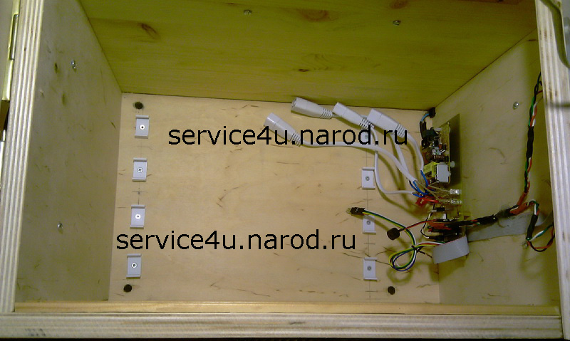
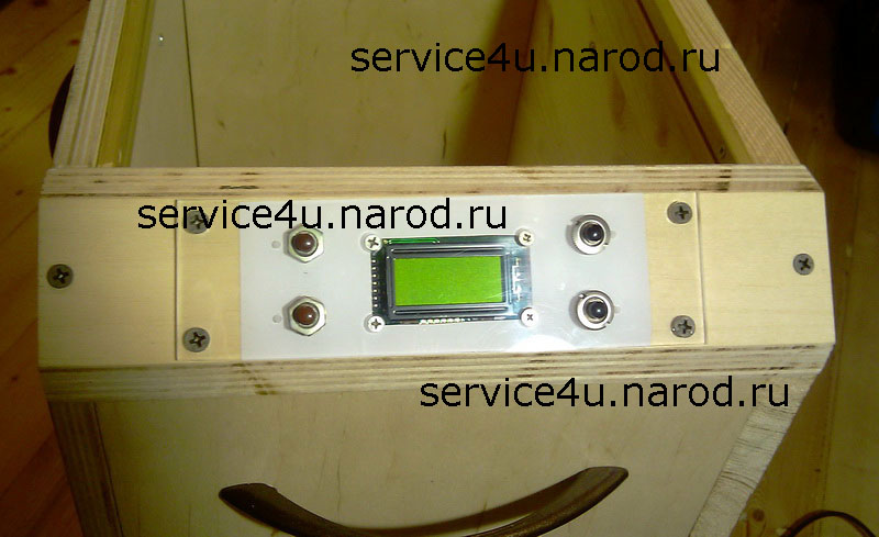
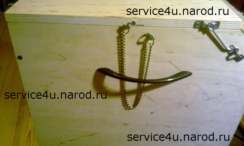
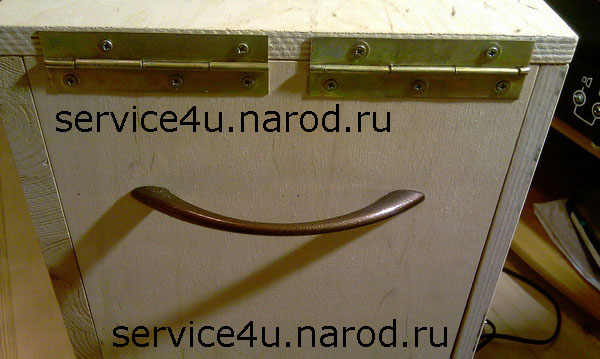
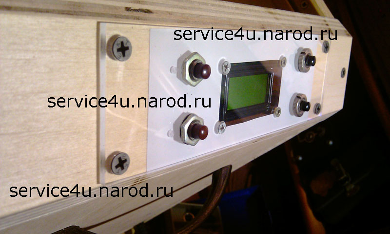
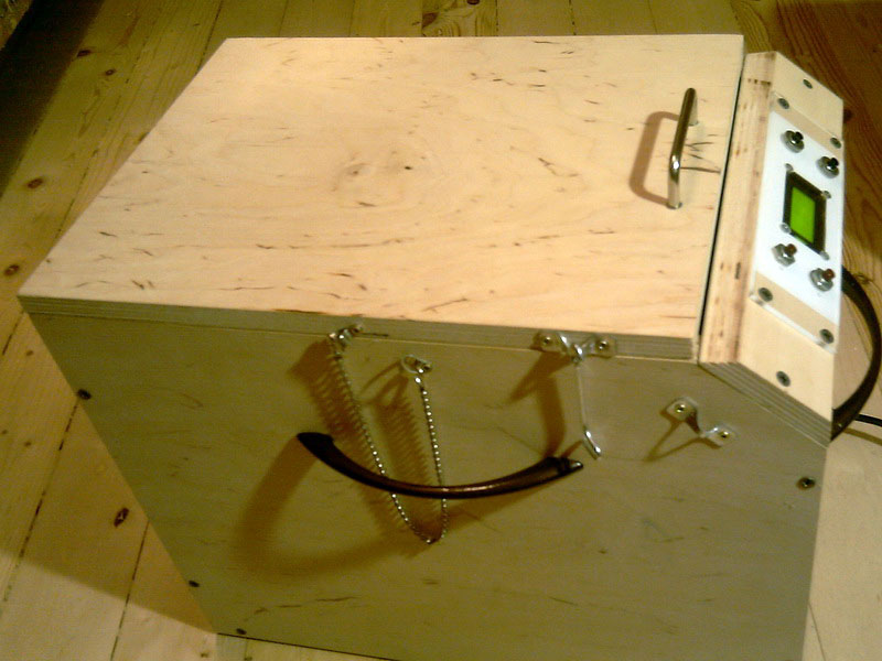
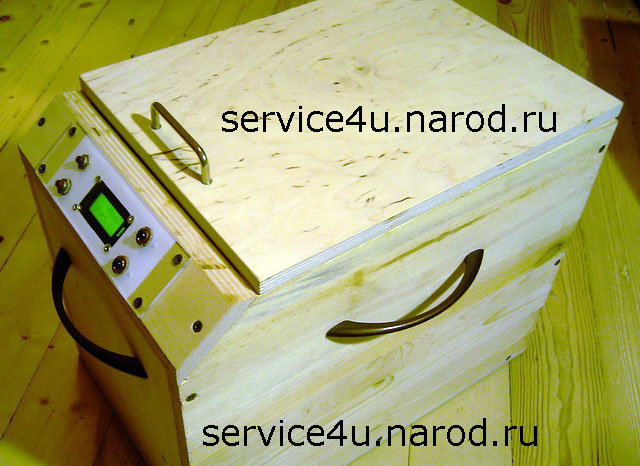
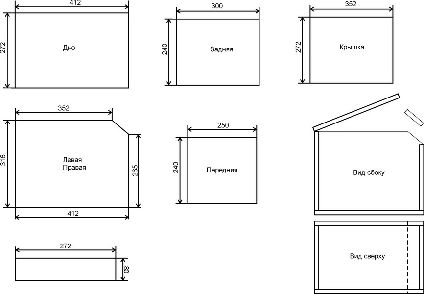
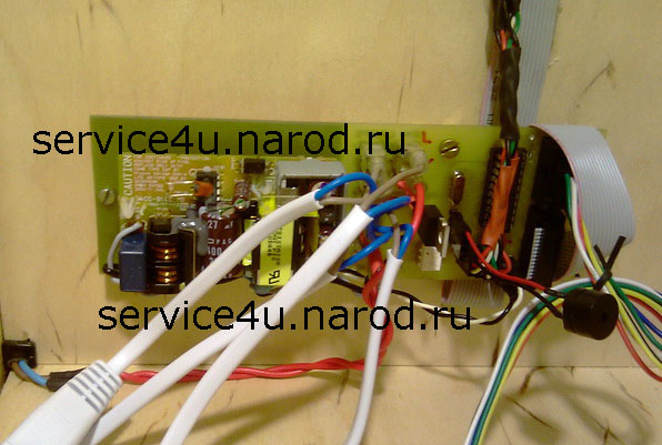
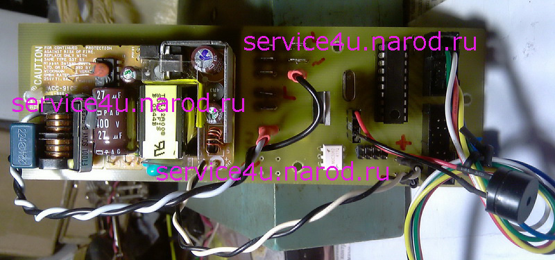
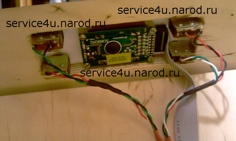
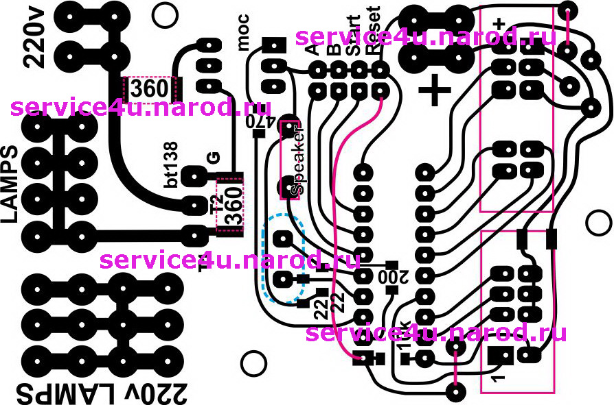
Time passes and we are not getting younger, but the hobby has chosen us. And while this hobby makes sense - we will take one height after another. At the same time, defining the following. Already the "Laser iron" method has receded into the background, although it is too early to write it off. If you have a stable source of coated printing paper, then there will be no problems with the iron and laser printer method (as I had). And the pages from glossy magazines that most of us use to make printed circuit boards did not suit me from the very beginning In addition, it is very important to power the lamps correctly. You can take a 4x18W electric ballast, plug in 4x8W lamps and hope that the lamps last longer than you think. But this is a big question mark. If you decide to follow the path of using UV lamps of the type I have, pay attention to the proper nutrition of the lamps. UV lamps test COntrol panel Top cover opening angle limiter One of the carrying handles. hinge Wall with front panel Side view Side view Case drawing AVR ATtiny2313 / external crystal 16MHz / BT138-600 / MOC3061 / SC0802 are the key elements of the circuit. I took the 5V / 2A power supply from the Sony PSP2 power supply, and the 220V cable from it. There are no toggle switches for on / off, so when the plug is plugged into the outlet, the timer immediately turns on and we see the inscription on the screen - 10sec Start? If you press the "Start" button, the device will turn on the UV lamps. At the end of the time interval, the UV lamps will turn off. "Press Reset" will appear. We press the reset button. The sausage in the top line runs and a request appears to start the device with the previous time interval. The time interval is recorded in EEPROM, and it is set by two buttons "+" and "-". There are two more buttons on the control panel of the device - "Reset" and "Start".
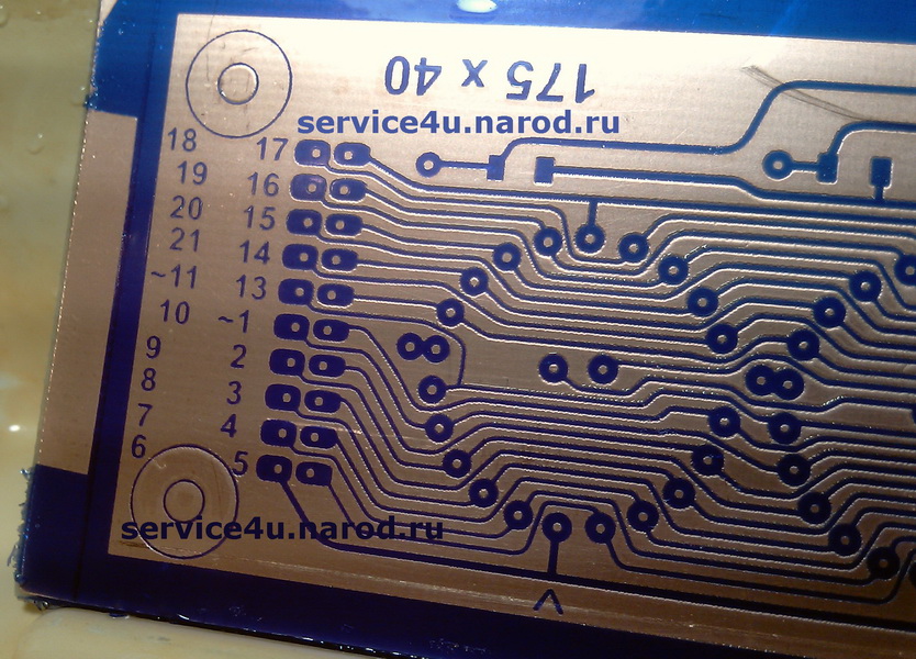
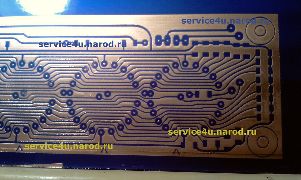
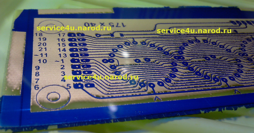
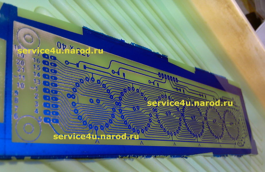
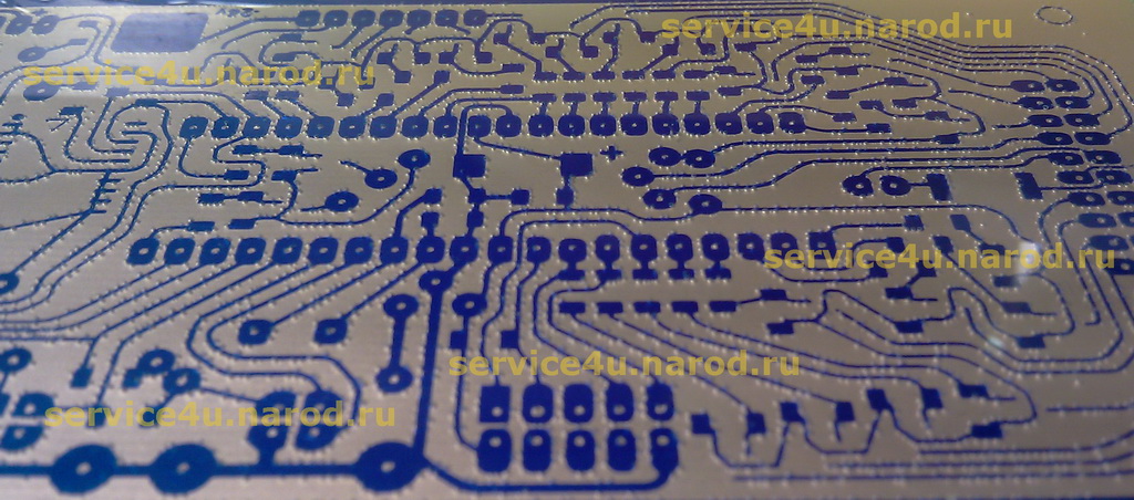
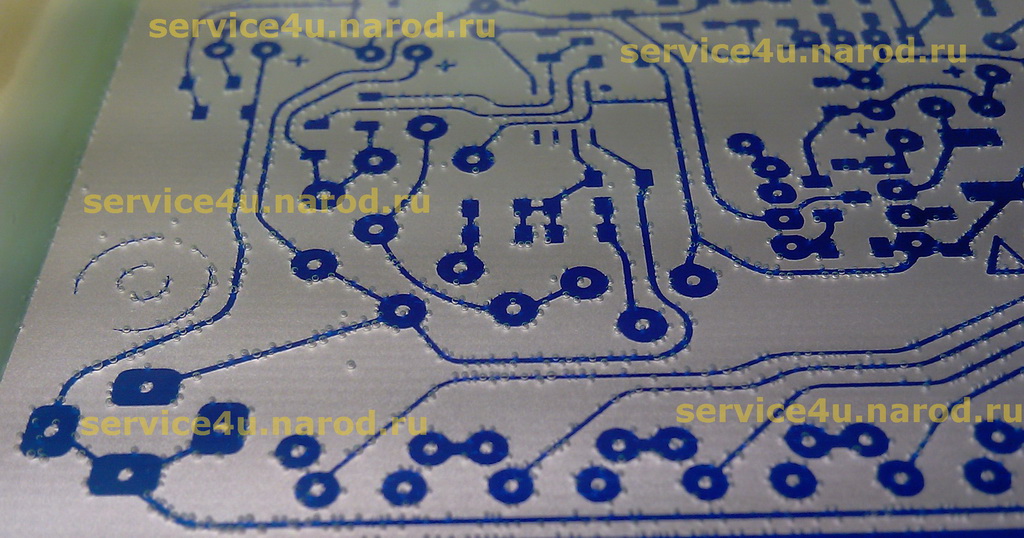
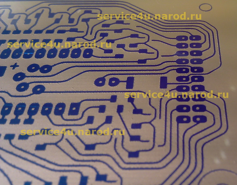
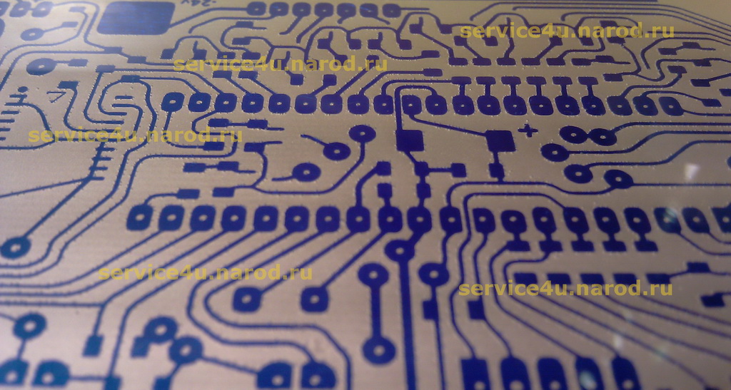
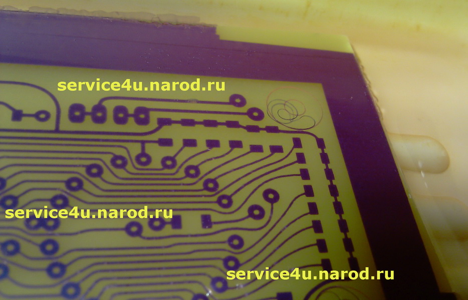
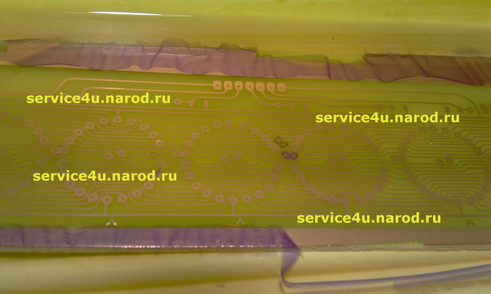
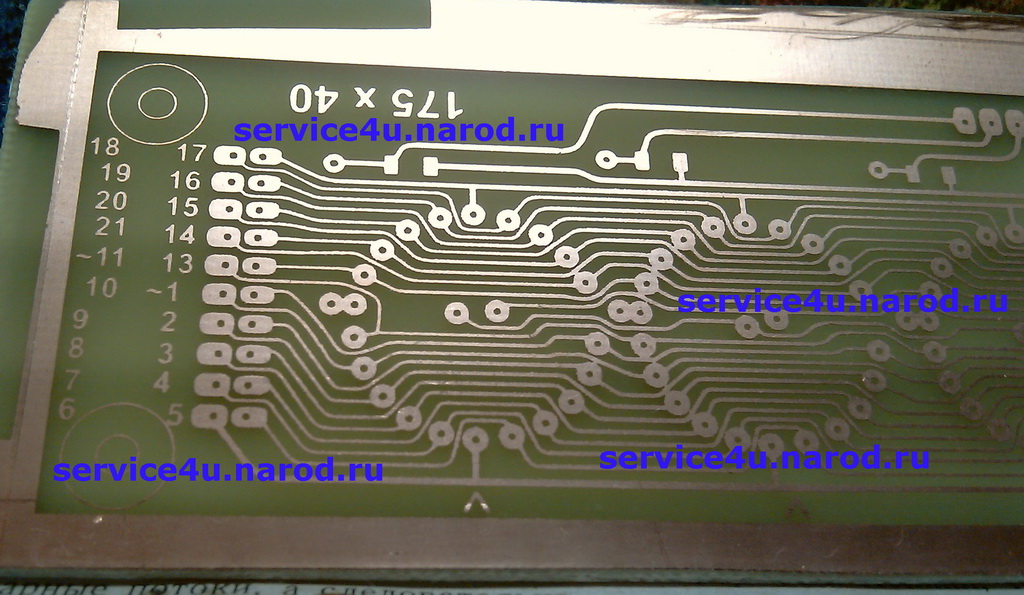
Timer pcb Timer pcb LCD and buttons inside Timer pcb routed on test Here it is - the gap in technology and quality of printed circuit boards We need four substances: The applied photoresist before etching the board The applied photoresist before etching the board etch the board almost etched the board The process of etching the board in ammonium persulfate The process of etching the board in ammonium persulfate The process of etching the board in ammonium persulfate The process of etching the board in ammonium persulfate drain cleaner effect drain cleaner effect finished After the board has been etched, pour the ammonium persulfate solution into a suitable container. We rinse the bath after etching, we also wash the board. Next, pour liquid into the bath from a vessel with a cheerful children's name "Pink Mole" (used to clean pipes). We pour not much - just so that the board is covered with this liquid. A few minutes are enough and the effect will not keep you waiting. Do not stroke the board with a brush - the "Pink Mole" dissolved my brush, turning it into a remnant of hair. After that, I began to use washing the brush in water in between stroking the handkerchief in "Pink Mole". Often at this stage, a solution of soda ash is used, with which the FR was bled first, simply, you need to keep the board in the solution longer and the FR is completely etched. You can replace the ammonium persulfate solution with the good old ferric chloride. And soda ash - on silicate glue. The advantage of silicate glue is that it is difficult to overexpose the board with the FR in it - it bleeds the FR very gently and slowly. In this case, you will get a new technology on old components. I will say that I do not plan to return to ferric chloride. Of course, some nuances are visible, next time with such a density of tracks and such a width, these defects will have to be eliminated after developing the FR before etching it.
1. paper is too thin, which is why the entire template always changes in linear dimensions when heated - it shrinks to the middle of the board, trying to turn into a point. To an infinitesimal point. You can easily get rid of this drawback - I warmed up the paper before printing the template in a laser printer. I just sent a blank page for printing, a couple of times, so that the paper "sat down". Used this method when making pcb for ISA connector for ZX clones that have ZX-BUS. It turned out well, but, {censored}, warming the paper twice - well, its {censored}. In addition, all the same, the paper "sat down" and had to be leveled with a needle from a syringe.
The use of an iron with steam, in the sole of which there are holes for the release of steam, does not have an effect for the entire duration of the template heating procedure. At the very beginning - yes, everything seems to be going well, the paper "does not shrink", but in the end, by the end of heating, shrinkage appears.
2. as a result, permanent smearing of the hardened toner over the textolite. Constantly before etching it is necessary to touch up with a needle from a syringe.
3. select the temperature conditions for the iron and the heating time of the board, depending on the size of the board. And all this still depends on the width of the tracks on the board.
The best result is to wrap excess paper (at least across the width of the board) under the edges of the board. This is true for boards of any size.
About double-sided boards, I will only say that I made them using the iron method on each side in turn, because. we have uncontrolled template compression on both sides of the board. I moored one side, drilled two holes, aligned the template on the second side with these reference holes and moored the second side. But all the same, I had to fix something every time, to scratch the foil with this needle from the syringe, but from both sides of the board. To eliminate the shortcomings of the print, I also used nail polish.
I decided to switch to photoresist. The question of solution required only one thing - with what and how to illuminate? I have a UV lamp from the times of the USSR, with which I erased UV ROM for ZX-Spectrum. But I decided not to use it - I left it in reserve. Another option is a UV lamp with an E27 base for a regular cartridge. I did not like this idea - something capital and solid was required. Good option for UV LEDs. Then they would need about 200 pieces. You can make two plates (for a double-sided board) to illuminate both sides at the same time. At the same time, a small problem arises in the manufacture of a driver, a case (collective farming on our knees is not our method). The idea is not bad, but the idea of using long UV flasks captured me completely.
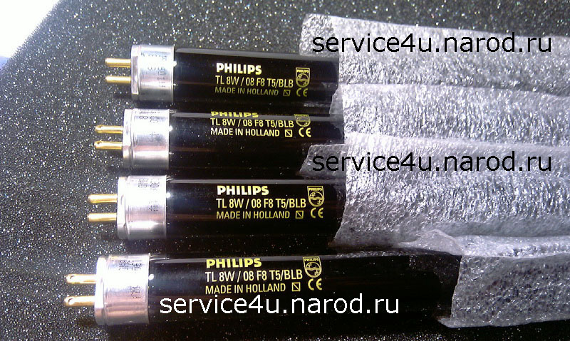
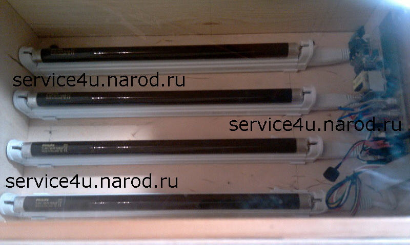
I bought Philips UV lamps at the city virtual flea market. After reading several pages of forums dedicated to the power of fluorescent lamps, it became clear - you can’t get off that easy. You could just buy at a virtual flea market such as chokes of the required power for my number of lamps, connect and enjoy life. But not in my case - the power of each lamp is 8W, there were no chokes (electronic ballasts) for such power. An option flashed - from 9W lamps with an E27 base, remove the converters and attach them to my lamps. And this is to separately buy 8 G5 cartridges, somehow attach them to the bottom of the bath, scatter the wires and pull them to the converters and still link and attach all this to the timer. Not good!
And here I thought about the lamp, in which these fluorescent lamps are inserted. What is he marking? What is the name of? And lo and behold - a couple of seconds of searching and voila - a well-known brand CAB28A lamp. Accurately searched with an 8W converter. Immediately with a wire, fasteners (2 types) and a connector included. Give 4!!!
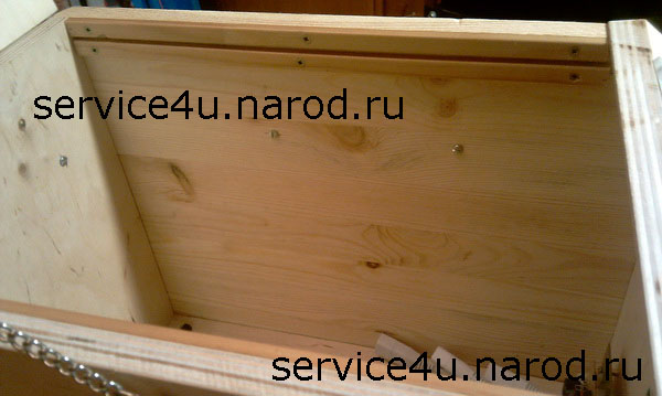
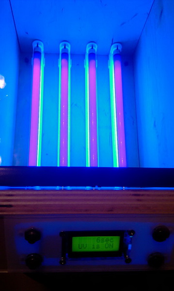
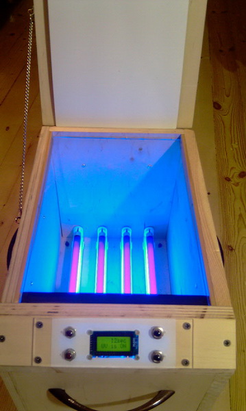
I wanted to attach them to the case from the old scanner, but did not because of the fact that uneven illumination of the template is possible due to the insufficient height of the glass above the level of UV radiation. I decided to make a capital body for uniform illumination of the template. Plywood 15mm thick - just right. And it also required a device to control the exposure time of the template - a timer. I calculated the size of the bath for illumination. I gave it to work, for cutting. After the repair, there were pieces of platband made of solid pine, slightly stained, walnut 5%. I made guides for glass from a flatbed scanner. Installed on both sides. I installed a cap hook on the side wall for stable fixation of the top cover in the process of carrying the UV bath. I also added a chain to secure the top cover in the open position. Furniture handles for transportation are installed on 4 side walls. On the top cover - for opening. But the best thing about the design will tell the photo.
Немного о таймере.
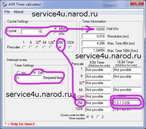
The AVR Timer Calculator program is designed to work correctly with AVR microcontroller timers. I will say a few words here. The program interface is intuitive:
- entered the clock frequency of your quartz;
- selected timer scale;
- entered the required time interval of the timer (in my case - 1 second);
- look at the bottom of the screen on the right to the line circled with a double frame - 3036 is the initial value of the timer. The timer is 16 bits (the column is signed on top) and after every 65535 pulses it overflows and resets. For a delay of 1 second, our timer must be reset every (65536-3036) pulses at a quartz frequency of 16 MHz and a timer scale of 256. If you click with the mouse in a line with a double frame, you will get a BAS-CODE, which will express the organization of your time exposure. Click the "Copy" button and paste it into your program.
: : Source (BASCOM) : :
: : Proteus File : :
: : Firmware : :
: : AVR Timer : :
Photoresist UV PCB making
- Soda ash;
- Ammonium persulfate;
- Pink Mole (drain cleaner);
- Water.
I didn’t sand, I just bought a smooth non-scratched textolite on the market. The board before knurling the photoresist (FR) was washed by a special. means. I used some sort of plumbing cleaner. It perfectly removed all the fat, you don’t need to procrastinate for a long time - a couple of movements, washed off. Wipe with a lint-free cloth.
Cut off a piece of FR a little larger than the board. Remove the thin protective film from the inside of the tube. When the FR tries to roll up into a tube, then inside this tube there is the surface that the FR should be rolled onto the board. Without allowing dust and villi, we roll the FR - at the same time we pull the lower protective film from under the FR and with a cloth along the width of the board with uniform translational movements we press the FR from above to the textolite. Squeeze out noticeable air bubbles with your fingers.
Further, if there is a laminator - we use a laminator, if not - a good old iron (where would we be without it, so many years together, you won’t remember without tears ...). Laminator or iron - we put our scarf with knurled FR into a page of paper folded in half with a density of 80 (usual office paper for laser printers) and run this sandwich into a heated laminator. I just smoothed it slightly with an iron, the temperature of the iron was at "2". Literally, a couple of movements, without pressure, warm up slightly so that the FR sticks to a warm pcb.
I printed the pattern on an inkjet. On transparent film. One side of the film is rough, so it should be printed on it. I printed two templates to superimpose one on top of the other (we match exactly on a light table) and get a consistently opaque black as a result. We apply the template to the FR. Let's start our setup. In my case, the exposure time is 2 - 4 minutes. We put in the installation for illumination. We light up. We take out. ...and we understand that this is it, comrades! This is it, the same quality of factory-made PP.
It lit up just fine! I do not provide photos. Below on the page there is a photo of the finished board and intermediate steps. I took half a liter of warm water and 125g. soda ash. Stirred. Remove the protective film from the FR. We put our handkerchief in a bath with a solution of soda ash. With a brush or toothbrush, slowly drive over the surface of our board. You can also use your fingers - it feels like very strongly soapy water to the touch. Do not forget to control the process of descent of the FR in unlit places. You can do this - lightly rubbed the handkerchief, washed it under running water and assessed whether the FR came down to the foil or not. If not, put the handkerchief back into the soda ash solution. If it came down, we wash the board, check our future tracks. We put the board to dry (a couple of minutes). Drain the soda ash solution into a suitable container. Rinse the bath before etching the board.
I took half a liter of warm water and 125g. ammonium persulfate. Stirred. Removed the protective film from the FR. I put the handkerchief in the solution. And with a brush, we begin to slowly stroke the scarf (often found on the Internet in this role is a toothbrush). You should pay attention to the air bubbles, which are clustered purely along the conductors. It is believed that these bubbles are underetching the FR and should be removed from there. What I, in fact, was doing, slowly stroking my charm future scarf with a brush. A few photos below.