AVR Termometers
"Excuse me, can you tell me how many degrees below zero now?"
"Operation "Y" and other Shurik's adventures"
Currently {2003}, you can increasingly find a variety of computer accessories on the shelves in online stores and on the market. The Thermaltake Hardcano series of accessories provides a wide range of interface devices as well as control/cooling/etc devices. A couple of weeks ago I saw Thermaltake Hardcano 7 on the market. What is it? This is an aluminum plug for a 5.25 inch computer bay, on the front panel of which there are connectors for one IEEE1394 port and two USB ports, a three-position slide switch for adjusting the fan speed (L-M-H /), as well as a thermometer LCD panel. The thermometer is powered by a coin cell battery. All fasteners and cords are included. This item costs $20. Well, ports in so far as there are not so many users who connect / disconnect digital cameras, scanners, mice via the USB interface every day at home. The speed switch for fans additionally installed in the computer system unit (FanBus) is relevant for overclockers who try to squeeze as many megahertz out of their hardware as possible, and which, in turn, needs more intensive cooling and good air circulation inside the system unit. Successful technical solutions available for manual manufacturing (at home) can be found much more on English and Russian-language Internet resources dedicated to this topic, besides not only FanBus, but also RheoBus, etc. But the thermometer is a necessary thing. But paying $20 for a thermometer isn't good. And the idea came to my mind without leaving the counter of the stall: to solder the thermometer myself. And better two thermometers - like Thermaltake Hardcano 2, which served as a prototype.
But you will have to configure them more carefully, because. discrepancies in the readings of two Thermaltake Hardcano 2 thermometers (ceteris paribus) can be up to 0.8 degrees Celsius (see article here).
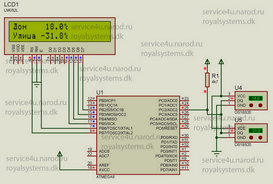
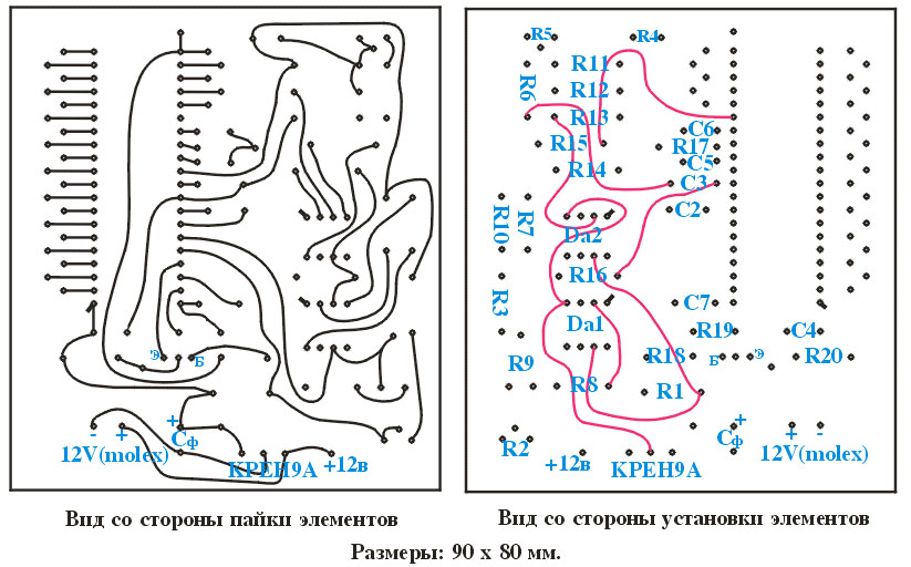
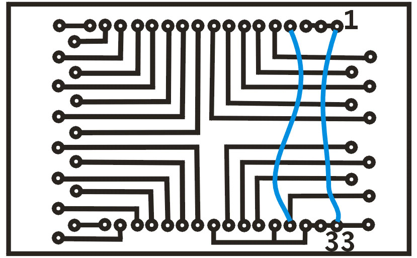
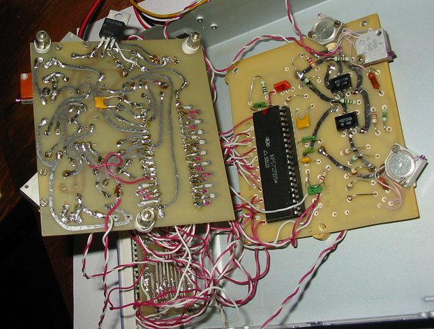
I have been doing radio engineering for a very long time - so I have experience. Within 3 days, about a dozen digital thermometer circuits were reviewed, and, as the most suitable, the circuit diagram of this thermometer was chosen. Judging by the declared parameters - this is what you need. Yes, and the element base of those times is now publicly available. The article shows a drawing of a printed circuit board, but I did not repeat it - I developed my own. The next day, all the necessary radio components were bought at Zhdany (for everything - about everything I spent $ 10, which is two times cheaper than the prototype) and three printed circuit boards were made (two for two thermometers, and the third for LCD panels ). Below are the topologies of printed circuit boards. How to make a printed circuit board at home can be read on the Internet. Here you can read how I did it at home for many, many years.
Further, everything is simple: assembly, adjustment, testing, installation. Assembly didn't take as long as setup. The process of setting up and testing the thermometer is described in the original source. The only thing I want to focus your attention on is the relationship between atmospheric pressure and the boiling point of water. Our thermometers must be set exactly as we're going to measure the temperature of the chips of our "iron friend", not the environment. I measured atmospheric pressure with a barometer, placing it on a stand near a glass of boiling water at the same level as the surface of the liquid. Atmospheric pressure on my table was 728 mm Hg. In [A.S.Enokhovich, M., Enlightenment, Handbook of Physics and Technology, 1989, p.115] the boiling point of water is 100 degrees Celsius at atmospheric pressure 760 mm Hg. We have a significant difference in the two values of atmospheric pressure (as much as 32 mm Hg, which is 1.5 degrees Celsius). I wonder at what temperature the water will boil in our case? Not at 100 degrees. Celsius is exactly right. Having resorted to the help of a mathematical apparatus, I received that at an atmospheric pressure of 728 mm Hg. water boils already at a temperature of 98.28 degrees Celsius, and the calculation by the formulas gives the boiling point of water at 100 degrees Celsius only at atmospheric pressure 775.0934286 mm Hg. An industrial thermometer placed in a glass of boiling water showed 98.4 degrees Celsius. To be honest, I trust math more than some [reference book]. If there is no barometer, then you can find out the value of atmospheric pressure, for example, at the Hydrometeorological Center. The formulas for calculating are somewhat large, but they are still worth paying attention to:
P=((EXP(85,187965+10,280025*T-11,487758*LN(1000*T)-7,821541/T))*760)/1,01325 (1)
T=(t+273,15)/1000 (2)
* - (asterisk) denotes multiplication.
t is the temperature in degrees Celsius.
Thus, we substitute the temperature in degrees Celsius into formula (2) and substitute the resulting value into formula (1). Those. we get the desired pressure P. In order to find out at what temperature water should boil at a given pressure, it is enough to "drive" these two formulas into Excel and by selecting the temperature to achieve the minimum discrepancy between the current atmospheric pressure {in mmHg} and calculated. Our task is to achieve a minimum discrepancy in the readings of two thermometers (ceteris paribus). My discrepancy in the readings was either absent at all, or was 0.1 degrees Celsius, and this corresponds to the temperature measurement error [source] declared by the author in the middle of the temperature range. The entire range of measured temperatures [source] is -60...+100 degrees Celsius.
In fact, the thermometer is able to measure the temperature of both "hot" objects and "cold" ones. My thermometers easily measured the temperature of the soldering iron tip during heating and showed 175 degrees Celsius. The temperature of the "warmed up" vapors of liquid nitrogen was almost as easily measured - it amounted to - 78 degrees Celsius (control measurements were carried out in parallel using a thermocouple at the same point with a temperature sensor), although the temperature of liquid nitrogen itself is - 190 degrees Celsius nevertheless, he did not dare to dip the temperature sensor into the liquid because of the threat of its destruction and, as a result, a small local boiling of liquid nitrogen with the release of drops (otherwise it would have been like in the movie "Terminator 2" :-). As you can see, the range of measured temperatures is to some extent determined by the type of temperature sensor used, but there are also limitations in the range laid down in the circuit diagram of the thermometer: it is really possible to measure temperatures in the range of -100 ... + 199.9 degrees Celsius with the appropriate temperature sensor such as thermocouples. But when using a thermocouple, you will have to significantly modify the circuit diagram of the thermometer.
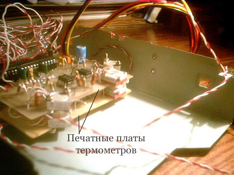
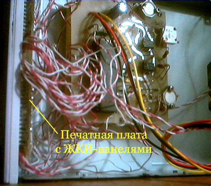
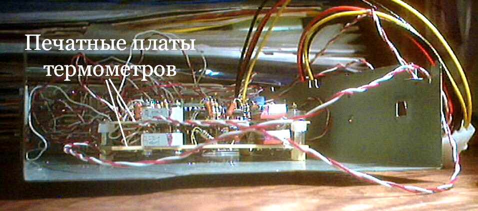
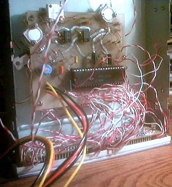
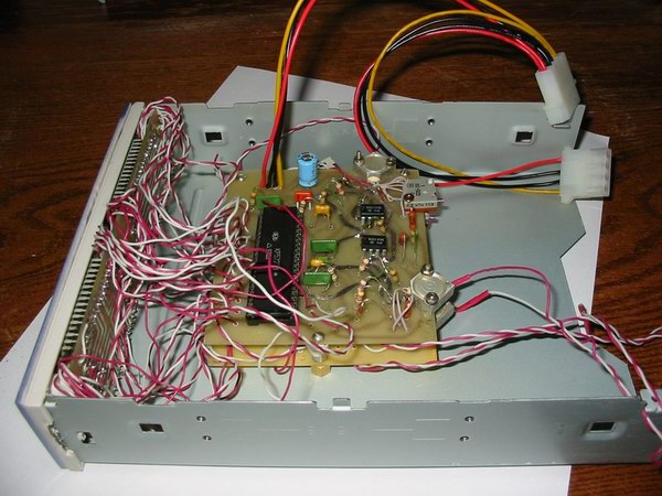
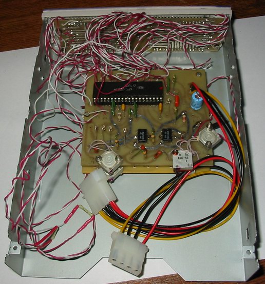
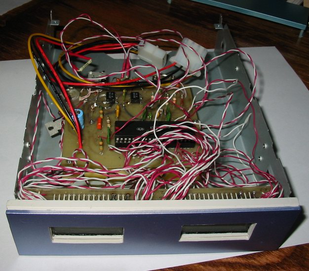
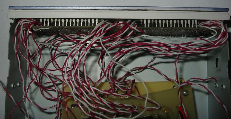
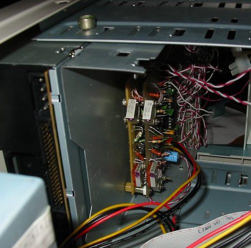
To install the thermometer boards, I used a metal chassis from a damaged CD-ROM drive. Attached to the front of the chassis is an empty blank from your system unit with dremel-cut windows for LCD panels, on which a printed circuit board with LCD panels is pre-installed. As height limiters (racks), polyethylene bushings of filters from "West" cigarettes were used. On the plug, to which a printed circuit board with LCD panels is attached with screws, a bezel with machined recesses on the inside under the screw heads is attached.
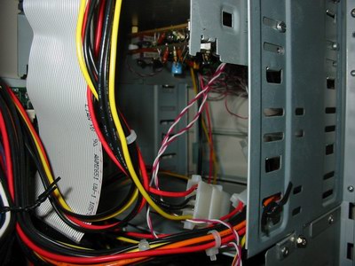
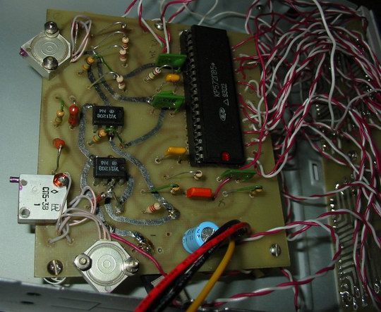
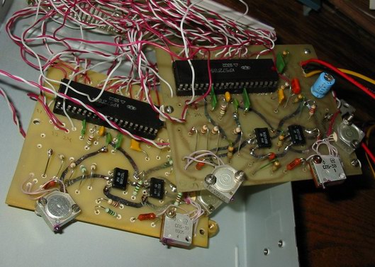
I used dichloroethane adhesive to attach the bezel. The false panel can be omitted if the LCD panels are attached to the plug using plastic racks attached to the plug from the inside with some kind of glue, for example, based on the same dichloroethane. The printed circuit boards of the thermometers are attached directly to the chassis on brass posts. Power is supplied to one of the thermometer boards via MOLEX - a "male - two female" adapter, in which the power leads from one "mother" are soldered directly to the printed circuit board. To power the thermometers, 12V leads are used. To obtain a supply voltage of 9V, a ST7809A stabilizer was used. If you want the temperature to be displayed even when the computer is powered off, you can connect a Krona battery through a diode.
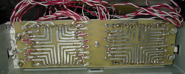
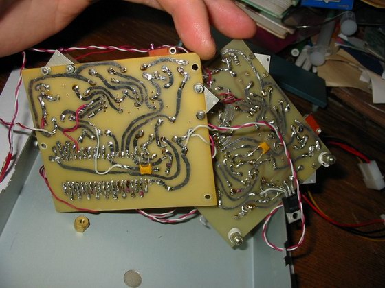
pcb
pcb
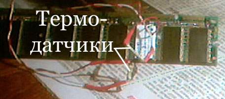
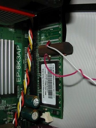
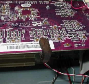
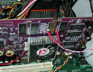
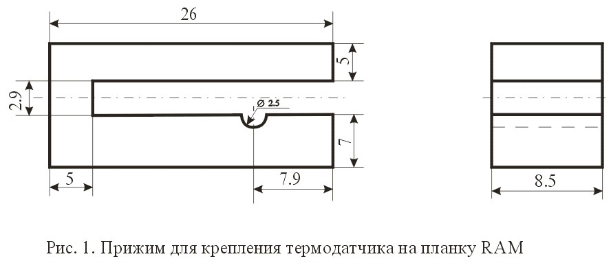
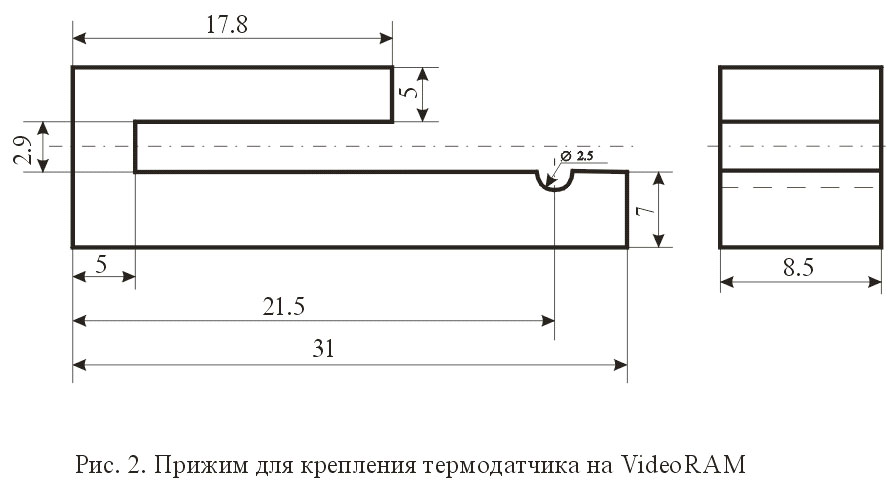
Thermal sensors are attached wherever you want. The simplest device for fastening temperature sensors is to press the temperature sensor with a wooden clothespin, but it needs to be significantly improved. To fasten the temperature sensors, I used a piece of cylindrical ebonite with a diameter of 16 mm with a round hole drilled perpendicular to the longitudinal axis of symmetry for the radius of the thermistor. Along the longitudinal axis of symmetry, a groove was also machined by a dremel for mounting the sensor from the end of the printed circuit boards. This ensures maximum ease of installation on the RAM bar and on VideoRAM from the end of the video card printed circuit board, as well as a snug fit of the thermal sensor to the microcircuit (when using a clothespin, the clamping force is noticeably higher, so look - do not overdo it - you can crush the thermal sensor this way) and secure fastening the entire system as a whole. The clamp for attaching the sensor to the video card (I have a Radeon 9100 noname) has one "tooth" cut off. on my video card, video memory chips are installed in "fading" cases, and on the reverse side, under the chips, a lot of unpackaged trifles are soldered. Your memory can be in BGA packages, and mirrored on both sides of the printed circuit board. In this case, a thickness of 16 mm may not be enough.
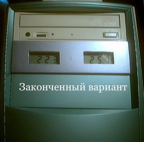
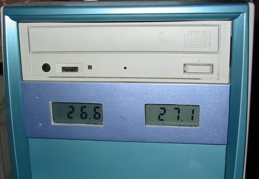
Another option for attaching a temperature sensor is office "crocodiles", which fasten a thick stack of pages of various formats. In this case, you will have to lay a solid, thin dielectric between the bottom of the clamp and the printed circuit board of the video card in order to avoid failure of the latter. Plastics for the manufacture of clamps are not suitable, because. we need that periodic heating / cooling does not lead to a change in the linear dimensions of the temperature sensor clamp. You can, of course, use caprolon (also a dielectric), but this is a very hard material and its processing is very laborious. The width of the inner groove, sawn along the longitudinal axis of symmetry of the clamp, should be selected practically - the application of insignificant efforts when "putting" the clamp on the memory bar can cost a lot due to the scanty difference in the mounting height of memory chips on the bar of 0.055 mm. The most convenient way is to fasten the temperature sensor between the fins of the radiators for cooling chipsets of motherboards, video cards, etc. Now, when everything is installed properly and everything works, it can be seen that at standard frequencies (250/250) the VideoRAM temperature is 31.7 degrees Celsius, and at higher frequencies (300/285) the VideoRAM temperature is 38.3 degrees Celsius when running 3DMark2001SE / 1024x768x32 /. Temperature RAM /Mtec 256Mb/ 40.4 degrees Celsius and 49 degrees Celsius, respectively. In the photo, the indicator on the left shows the VideoRAM temperature, on the indicator on the right - the temperature of the operational RAM a few minutes after turning it on.
You can, of course, use caprolon (also a dielectric), but this is a very hard material and its processing is very laborious. The width of the inner groove, sawn along the longitudinal axis of symmetry of the clamp, should be selected practically - the application of insignificant efforts when "putting" the clamp on the memory bar can cost a lot due to the scanty difference in the mounting height of memory chips on the bar of 0.055 mm. The most convenient way is to fasten the temperature sensor between the fins of the radiators for cooling chipsets of motherboards, video cards, etc. Now, when everything is installed properly and everything works, it can be seen that at standard frequencies (250/250) the VideoRAM temperature is 31.7 degrees Celsius, and at higher frequencies (300/285) the VideoRAM temperature is 38.3 degrees Celsius when running 3DMark2001SE / 1024x768x32 /. Temperature RAM /Mtec 256Mb/ 40.4 degrees Celsius and 49 degrees Celsius, respectively.

Termometer Ver.Pro#1
22.05.2017 Added

: : Firmware : :
: : Source code : :
Termometer Ver.Pro#2
23.05.2017 Added